You are viewing the documentation for an older COMSOL version. The latest version is
available here.
When ray intensity or power is solved for, thin dielectric films can be used to change the reflection and transmission coefficients at boundaries. Individual dielectric layers can be applied to a boundary by using the Thin Dielectric Film subnode, which can be added to the
Material Discontinuity and
Wall nodes. The
Thin Dielectric Film subnode can be added to the same boundary multiple times to create multilayer films. In general, the thickness of these thin dielectric films is comparable in magnitude to the wavelength of the rays; a minimum requirement is that the thickness of each layer is much less than the coherence length of the incident rays.
When the Thin Dielectric Film feature is used to model dielectric layers, the equivalent Fresnel coefficients for ray propagation through the layer are computed using a recursive algorithm. These equivalent Fresnel coefficients are, in general, complex-valued reflection and transmission coefficients that account for the phase delay and amplitude change in the reflected and transmitted rays resulting from the multiple reflections that the ray undergoes within the dielectric layer, all of which are considered to be coherent with each other. As these multiple reflected and refracted rays propagate into the domains adjacent to the film, they can interfere constructively or destructively with each other, which affects the total electric field amplitude that propagates into each domain. This is illustrated in
Figure 3-13 below. Due to the rays’ capability to interfere constructively or destructively with each other, the optical thickness of the thin film has a significant effect on the amplitude and phase of the reflected and refracted rays.
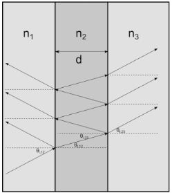
Consider, as shown above, a thin film of thickness d and refractive index
n2 bounded by semi-infinite domains with refractive indices
n1 and
n3. Also consider a linearly polarized ray with electric field amplitude
E0 that propagates through the domain of refractive index
n1 and interacts with the thin film. Let the coefficients of refraction and transmission for a ray moving from the domain of refractive index
na to the domain of refractive index
nb be denoted
rab and
tab, respectively. When the ray arrives at the film, the refracted ray undergoes a series of reflections at the boundaries between the film and either adjacent domain. Following
Ref. 6, the amplitudes of the refracted rays in either domain form a pair of converging geometric series with sums
for rays entering the domain of refractive index n3. The angle
β is the phase delay that is introduced when a ray propagates from one surface of the film to the other,
(3-13)

where λ0 is the free-space wavelength and
θ2 is the angle between the wave vector of a ray within the thin film and the normal to the film. The dielectric film can be modeled as a material discontinuity with transmission and reflection coefficients
teq = E3 / E0 and
req = E1 / E0.
The Material Discontinuity node includes options for automatic setup of single-layer films with specified reflectance
R or transmittance
T. In either case the layers are assumed to be nonabsorbing, so that
R + T = 1. To enable these options, select
Specify reflectance or
Specify transmittance from the
Thin dielectric films on boundary list, and then select the
Treat as single layer dielectric film check box.
The specified reflectance R of a thin film with refractive index
n is valid only for certain values of the angle of incidence
θi and free-space wavelength
λ0. After computing the Fresnel coefficients for rays entering and leaving the layer, the reflectance can be expressed as
Solving this expression for β and substituting the result into
Equation 3-13 yields
To automatically compute the refractive index and thickness of a single-layer anti-reflective coating between two dielectric media, in the settings for the Material Discontinuity node select
Anti-reflective coating from the
Thin dielectric films on boundary list. By default the anti-reflective coating is ideal, in the sense that is always has a reflectance of zero for rays of any wavelength and any angle of incidence. However, if you select the
Treat as single layer dielectric film check box, then instead the single-layer coating only has a reflectance of zero for rays at a specific angle of incidence
θi (SI unit: rad) and vacuum wavelength
λ0 (SI unit: m).
For oblique incidence, the refractive index of the ideal single-layer coating differs for s- and
p-polarized rays. For
s-polarized rays, the refractive index
n2 of a film between media with refractive indices
n1 and
n3 is
For p-polarized rays, the refractive index is
Either equation returns the value of n2 for which
r12 = r23 for rays of the specified polarization at the specified angle of incidence. An ideal anti-reflective coating is obtained when the magnitude of the equivalent reflection coefficient is
0. This can be obtained when
r12 = r23 and the phase delay
δ is equal to
π/2. Substituting this requirement into
Equation 3-13 yields an expression for
d:
Select the Repeat layer in multilayer films check box in the
Repeating Multilayer Films section of the
Thin Dielectric Film settings window to include the layer in the unit cell of a repeating multilayer film. It is possible to include some layers in the unit cell while excluding others. This could be used, for example, to ensure that a repeating multilayer film begins and ends with the same layer, since in this case the last layer is not included in any unit cell. However, the
Thin Dielectric Film nodes for all layers in the unit cell must be adjacent to each other in the Model Builder.
Enter a value or expression for the Number of repeating unit cells N in the
Material Discontinuity settings window. If there are
p Thin Dielectric Film nodes in which the
Repeat layer in multilayer films check box is selected and
q Thin Dielectric Film nodes in which the
Repeat layer in multilayer films check box is cleared, the total number of dielectric layers in the multilayer film
Nt will be
Np + q.
The recursive algorithm described in the section Computing the Fresnel Coefficients of Boundaries with Thin Dielectric Films is not well-suited to the calculation of the effective Fresnel coefficients for an extremely large number of thin dielectric films in a periodic arrangement. Instead, the following approach is used, in which the equivalent Fresnel coefficients are expressed in terms of the product of a large number of
2-by-
2 matrices.
Let the electric field amplitude of the incident, reflected, and transmitted rays entering layer m be denoted

,

, and

, respectively, where

. The ratios of the incoming and outgoing electric field amplitudes in consecutive layers
m and
m+1 are
Where Cm is a
2-by-
2 matrix:
where δm−1 is the phase shift within the layer, with
δ0 = 0.
For a multilayer film containing Nt layers including
N unit cells, the relationship between the incoming and outgoing electric field amplitudes can be expressed using the product of
Nt + 1 matrices and
Nt + 1 transmission coefficients:
where Cin is the product of the matrices for all layers prior to the unit cell,
Cout is the product of the matrices for all layers following the unit cell, and
Ccell is the matrix for all layers within one unit cell, including the interface between one unit cell and the next. Next an eigenvalue decomposition is performed on
Ccell:
where D is a diagonal matrix with nonzero elements
D11 and
D22. The ratio of the incoming and outgoing electric field amplitudes can then be expressed as


