You are viewing the documentation for an older COMSOL version. The latest version is
available here.
The Laminar Two-Phase Flow, Level Set (

)
interface contains an optional multiphysics coupling boundary feature,
Wetted Wall. It is an exclusive feature that overrides the
Wall feature in the Laminar interface as well as the
No Flow feature in the Level Set interface. It cannot be used in boundaries that have a
Flow Continuity feature in the flow physics interface or a
Continuity feature in the level set physics interface.
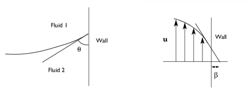
The Wetted Wall boundary condition is suitable for walls in contact with the fluid-fluid interface. When this boundary condition is used, the fluid-fluid interface can move along the wall.
For laminar flow, when the
Wall condition is set to
Navier slip, this boundary condition enforces the no-penetration condition
u ⋅ nwall = 0 and adds a tangential stress on the form
where  ,
, 
and
K is the viscous stress tensor.
β is the slip length. For numerical calculations, a suitable choice is
β = h, where
h is the mesh element size. The boundary condition does not set the tangential velocity component to zero. However, the extrapolated tangential velocity component is 0 at a distance
β outside the wall (see
Figure 4-1). When the
Wall condition is set to
Nonlinear Navier slip or
Asymptotic slip, the frictional force has a nonlinear dependency on the velocity (see
Wall).If the surface tension force is included in the momentum equation in
The Two-Phase Flow, Level Set Coupling Feature, the
Wetted Wall boundary condition also adds the following boundary force to enforce the contact angle:

The contact angle θw is defined as the angle between the fluid interface and the wall (see
Figure 4-1). For more information, see
Ref. 4 and
Ref. 5. In order to properly account for direction and yield stress, when using
Hatzikiriakos slip in the
Wall condition, the surface tension contribution has to be combined with the viscous stress in the expression for the slip velocity,
where  , K
, K is the viscous stress tensor, and
twall is a unit vector tangential to the wall, in the direction of the projected interface normal.
The contact angle θw can be defined directly or from Young's equation, which considers the components of the forces in the plane of the surface:
(4-1)

where γs1 is the surface energy density on the fluid 1 — solid (wall) interface and
γs2 is the surface energy density on the fluid 2 — solid (wall) interface.
The Label is the default multiphysics coupling feature name.
The default Name (for the first
Wetted Wall multiphysics coupling feature in the model) is
ww1.
When nodes are added from the context menu, select All boundaries (the default) or select
Manual from the
Selection list to choose specific boundaries.
The Translational velocity setting controls the translational wall velocity,
utr. The list is per default set to
Automatic from frame. The physics automatically detects if the spatial frame moves. This can for example happen if an ALE interface is present in the model component. If there is no movement
utr =
0. If the frame moves,
utr becomes equal to the frame movement.
Select Manual from
Translational velocity selection list in order to manually prescribe
Velocity of moving wall,
utr. This can for example be used to model an oscillating wall where the magnitude of the oscillations are very small compared to the rest of the model. Specifying translational velocity manually does not automatically cause the associated wall to move. An additional Moving Mesh interface needs to be added to physically track the wall movement in the spatial reference frame.
Translational velocity can also be set to
Zero (Fixed wall) to force
utr =
0. This is typically used in problems where the mesh is deforming or rotating, but we want the boundary to keep zero velocity. For example, in fixed walls tangential to a
Rotating Domain.
|
•
|
The Slip Length setting is per default set to Factor of minimum element length. The slip length β is then defined as  , where  is the smallest element side (corresponds to the element size in the wall normal direction for boundary layer elements) and  is a user input. Select User defined from Slip Length selection list in order to manually prescribe β (SI unit: m) .
|
|
•
|
Select an option from the Specify contact angle list — Directly (the default) or Through Young’s equation. For Directly enter a Contact angle θw (SI unit: rad). The default is π/2 radians. For Through Young’s equation enter values or expressions for Phase 1-Solid surface energy density γs1 (SI unit: J/m 2) and Phase 2-Solid surface energy density γs2 (SI unit: J/m 2).
|
