
|

|
1
|
|
2
|
In the Select Physics tree, select Optics>Wave Optics>Electromagnetic Waves, Frequency Domain (ewfd).
|
|
3
|
Click Add.
|
|
4
|
|
5
|
Click Add.
|
|
6
|
Click
|
|
7
|
|
8
|
Click
|
|
1
|
|
2
|
|
3
|
|
4
|
Browse to the model’s Application Libraries folder and double-click the file fresnel_lens_parameters.txt.
|
|
1
|
|
2
|
|
3
|
|
4
|
Locate the Units section. From the Length unit list, choose µm, to make all lengths in plots appear in units of µm.
|
|
1
|
|
2
|
|
3
|
|
4
|
Browse to the model’s Application Libraries folder and double-click the file fresnel_lens_zone_parameters.txt.
|
|
1
|
|
2
|
|
3
|
|
4
|
In the x text field, type x0 x0 x1 x1 x2 x2 x3 x3 x4 x4 x5 x5 x6 x6 x7 x7 x8 x8 x9 x9 x10 x10 x11 x11 x12 x12 x13 x13 x14 x14 x15 x15 x16 x16.
|
|
5
|
In the y text field, type y0 y1 y1 y2 y2 y3 y3 y4 y4 y5 y5 y6 y6 y7 y7 y8 y8 y9 y9 y10 y10 y11 y11 y12 y12 y13 y13 y14 y14 y15 y15 y16 y16 y0.
|
|
6
|
Locate the Selections of Resulting Entities section. Find the Cumulative selection subsection. Click New.
|
|
7
|
|
8
|
Click OK.
|
|
9
|
|
1
|
|
2
|
|
3
|
|
1
|
|
2
|
|
3
|
|
4
|
|
5
|
Click OK.
|
|
6
|
|
1
|
|
2
|
|
1
|
|
2
|
|
1
|
|
2
|
|
1
|
|
2
|
|
1
|
|
2
|
|
3
|
|
4
|
|
5
|
|
1
|
|
2
|
Select the object uni1 only.
|
|
3
|
|
4
|
|
5
|
|
6
|
|
1
|
|
2
|
Click in the Graphics window and then press Ctrl+A to select both objects.
|
|
3
|
|
4
|
|
5
|
|
1
|
|
2
|
|
3
|
|
4
|
|
5
|
|
6
|
|
1
|
|
2
|
Click in the Graphics window and then press Ctrl+A to select both objects.
|
|
3
|
|
1
|
|
2
|
|
3
|
|
4
|
|
5
|
|
6
|
|
7
|
Click to expand the Layers section. In the table, enter the following settings:
|
|
1
|
|
2
|
|
3
|
|
4
|
|
1
|
|
2
|
|
3
|
|
4
|
|
5
|
|
1
|
|
1
|
|
2
|
|
3
|
In the tree, select Built-in>Air.
|
|
4
|
|
5
|
|
1
|
In the Model Builder window, under Component 1 (comp1) right-click Materials and choose Blank Material.
|
|
2
|
|
3
|
|
4
|
|
5
|
|
1
|
|
2
|
|
3
|
|
4
|
|
1
|
|
2
|
|
3
|
|
4
|
|
5
|
|
6
|
|
7
|
Click OK.
|
|
8
|
|
9
|
|
10
|
|
11
|
|
12
|
|
13
|
|
1
|
|
2
|
|
3
|
|
4
|
|
5
|
|
6
|
Click OK.
|
|
7
|
|
8
|
|
9
|
|
10
|
Click OK.
|
|
11
|
|
1
|
|
2
|
|
3
|
|
5
|
|
1
|
|
2
|
|
3
|
|
4
|
|
1
|
In the Model Builder window, under Component 1 (comp1) click Electromagnetic Waves, Frequency Domain (ewfd).
|
|
2
|
|
3
|
|
1
|
|
2
|
|
3
|
|
4
|
Locate the Scattering Boundary Condition section. From the Incident field list, choose Wave given by E field.
|
|
5
|
|
6
|
From the Order list, choose Second order, to reduce the reflections from radiation incident with a nonnormal direction to this boundary.
|
|
1
|
|
2
|
|
3
|
|
4
|
|
5
|
Locate the Scattering Boundary Condition section. From the Order list, choose Second order, to reduce the reflections from radiation incident with a nonnormal direction to this surrounding boundary.
|
|
1
|
|
2
|
|
1
|
|
2
|
|
3
|
Click the Custom button.
|
|
4
|
Locate the Element Size Parameters section. In the Maximum element size text field, type lda0/Nmesh.
|
|
1
|
|
2
|
|
3
|
|
5
|
|
1
|
|
2
|
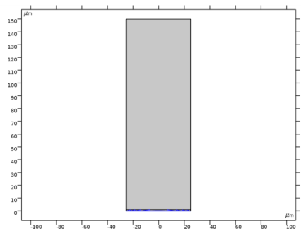
Select Domain 3 only. The simplest way to do this is to select entity 4 in the Selection box and then click the Remove from Selection (the minus sign) button in the Selection toolbar.
 |
|
3
|
|
4
|
Click the Custom button.
|
|
5
|
|
6
|
In the associated text field, type lda0/n/Nmesh.
|
|
1
|
|
3
|
|
4
|
|
1
|
|
2
|
|
3
|
|
4
|
Locate the Physics and Variables Selection section. In the table, clear the Solve for check box for Electromagnetic Waves, Beam Envelopes (ewbe).
|
|
5
|
|
1
|
|
2
|
|
3
|
|
1
|
|
2
|
|
3
|
|
4
|
|
5
|
Click
|
|
1
|
|
2
|
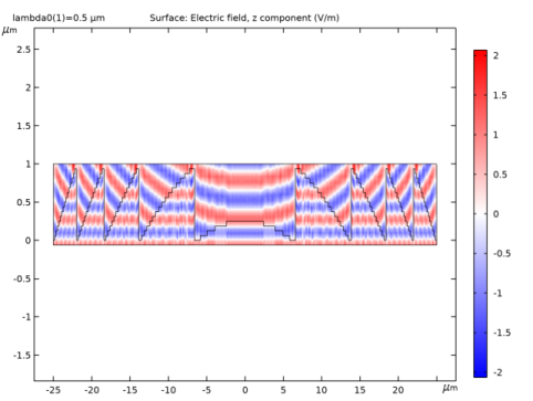
In the Settings window for 2D Plot Group, type Electric Field Amplitude (ewfd) in the Label text field.
|
|
1
|
|
2
|
|
3
|
|
4
|
|
5
|
|
6
|
|
1
|
|
2
|
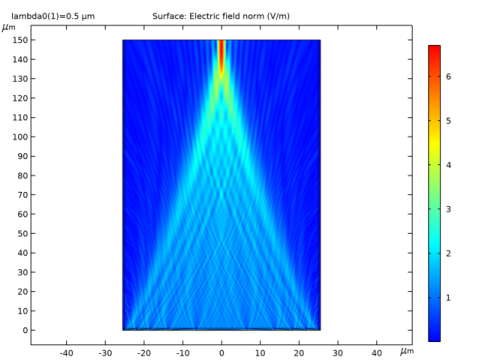
In the Settings window for 2D Plot Group, type Electric Field Norm Near Lens (ewfd) in the Label text field.
|
|
1
|
|
2
|
|
3
|
|
4
|
|
5
|
Click
|
|
1
|
|
2
|
|
1
|
|
2
|
|
3
|
|
4
|
|
5
|
|
1
|
|
2
|
In the Settings window for 2D Plot Group, type Electric Field Amplitude Near Lens (ewfd) in the Label text field.
|
|
3
|
|
4
|
|
5
|
|
1
|
|
2
|
In the Settings window for 1D Plot Group, type Electric Field Amplitude at Exit Plane (ewfd) in the Label text field.
|
|
1
|
|
2
|
|
3
|
|
4
|
|
5
|
|
6
|
|
7
|
|
1
|
In the Model Builder window, right-click Electric Field Amplitude at Exit Plane (ewfd) and choose Duplicate.
|
|
2
|
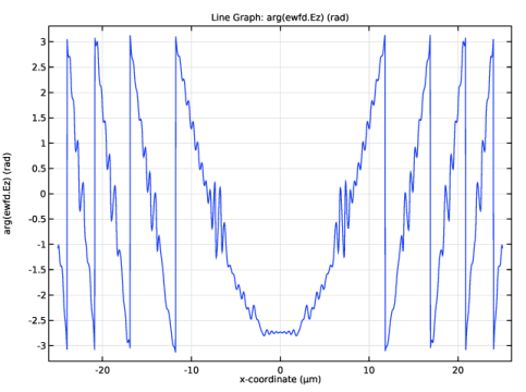
In the Settings window for 1D Plot Group, type Electric Field Phase at Exit Plane (ewfd) in the Label text field.
|
|
1
|
In the Model Builder window, expand the Electric Field Phase at Exit Plane (ewfd) node, then click Line Graph 1.
|
|
2
|
|
3
|
|
4
|
|
1
|
In the Results toolbar, click
|
|
2
|
|
3
|
|
4
|
|
5
|
|
1
|
|
2
|
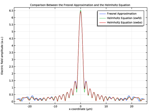
In the Settings window for 1D Plot Group, type Fresnel Versus Helmholtz Comparison in the Label text field.
|
|
3
|
|
1
|
|
2
|
|
3
|
Locate the y-Axis Data section. In the Expression text field, type 1/sqrt(lda0*f)*abs(intop1(ewfd.Ez*exp(-i*k0*x^2/(2*f))*exp(i*2*pi*dest(u)*x/(lda0*f)))).
|
|
4
|
Select the Description check box.
|
|
5
|
In the associated text field, type Diffraction integral.
|
|
6
|
|
7
|
|
8
|
|
9
|
|
1
|
|
2
|
|
3
|
|
4
|
|
5
|
|
6
|
|
8
|
|
9
|
|
10
|
|
11
|
|
1
|
|
2
|
|
3
|
|
4
|
In the associated text field, type x-coordinate (µm).
|
|
5
|
|
6
|
In the associated text field, type Electric field amplitude (a.u.).
|
|
7
|
|
8
|
In the Title text area, type Comparison Between the Fresnel Approximation and the Helmholtz Equation.
|
|
9
|
|
1
|
In the Model Builder window, under Component 1 (comp1) click Electromagnetic Waves, Beam Envelopes (ewbe).
|
|
2
|
|
3
|
|
4
|
|
5
|
|
1
|
|
2
|
|
3
|
|
4
|
|
1
|
|
2
|
|
3
|
|
1
|
|
1
|
|
2
|
|
3
|
|
4
|
Click the Custom button.
|
|
5
|
|
6
|
|
1
|
|
2
|
|
3
|
Find the Studies subsection. In the Select Study tree, select Preset Studies for Selected Physics Interfaces>Wavelength Domain.
|
|
4
|
Find the Physics interfaces in study subsection. In the table, clear the Solve check box for Electromagnetic Waves, Frequency Domain (ewfd).
|
|
5
|
|
6
|
|
1
|
|
2
|
|
3
|
|
1
|
|
2
|
|
3
|
|
1
|
|
2
|
|
3
|
|
4
|
|
5
|
Locate the Legends section. In the table, enter the following settings:
|
|
6
|
|
1
|
|
2
|
|
3
|
Click OK.
|
|
1
|
|
2
|
Copy the following code into the rebuildGeometry window:
|
|
1
|
|
2
|
|
4
|
|
1
|
|
2
|