|
|
|


|
1·10-3 Pa·s
|
||
|
1.81·10-5 Pa·s
|
||
|
m-1
|
|||||
|
m-2
|
2.48·10-12
|
1.09·10-12
|
0.94·10-12
|
|
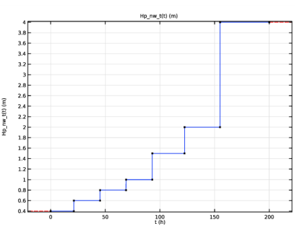
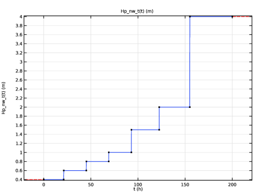
Pressure head (m water)
|
Start time (hours)
|
|
1
|
|
2
|
|
3
|
Click Add.
|
|
4
|
|
5
|
|
6
|
Click Add.
|
|
7
|
|
8
|
Click
|
|
9
|
|
10
|
Click
|
|
1
|
|
2
|
|
3
|
|
4
|
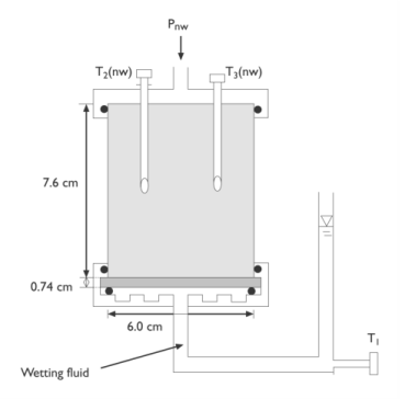
Browse to the model’s Application Libraries folder and double-click the file twophase_flow_column_parameters.txt.
|
|
1
|
|
2
|
|
3
|
|
4
|
Click Browse.
|
|
5
|
Browse to the model’s Application Libraries folder and double-click the file twophase_flow_column_interpolation.txt.
|
|
6
|
Click Import.
|
|
7
|
|
8
|
Locate the Interpolation and Extrapolation section. From the Extrapolation list, choose Nearest function.
|
|
9
|
|
10
|
|
11
|
|
1
|
|
2
|
|
3
|
|
4
|
|
5
|
Click to expand the Layers section. In the table, enter the following settings:
|
|
6
|
|
1
|
|
2
|
|
3
|
|
1
|
|
2
|
|
3
|
|
4
|
Browse to the model’s Application Libraries folder and double-click the file twophase_flow_column_air_water.txt.
|
|
1
|
|
2
|
|
3
|
|
4
|
Browse to the model’s Application Libraries folder and double-click the file twophase_flow_column_retention_model.txt.
|
|
1
|
|
2
|
|
3
|
|
4
|
Browse to the model’s Application Libraries folder and double-click the file twophase_flow_column_initial_conditions.txt.
|
|
1
|
|
2
|
|
3
|
|
5
|
|
6
|
Browse to the model’s Application Libraries folder and double-click the file twophase_flow_column_lower_layer.txt.
|
|
1
|
|
2
|
|
3
|
|
5
|
|
6
|
Browse to the model’s Application Libraries folder and double-click the file twophase_flow_column_upper_layer.txt.
|
|
1
|
In the Model Builder window, under Component 1 (comp1) right-click Materials and choose Blank Material.
|
|
2
|
|
1
|
|
2
|
|
1
|
|
2
|
|
3
|
|
1
|
In the Model Builder window, under Component 1 (comp1)>Darcy’s Law (dl) click Fluid and Matrix Properties 1.
|
|
2
|
|
3
|
|
4
|
Locate the Matrix Properties section. From the εp list, choose User defined. In the associated text field, type 0.25.
|
|
5
|
|
1
|
|
2
|
|
3
|
|
1
|
|
3
|
|
4
|
|
5
|
Locate the Matrix Properties section. From the εp list, choose User defined. In the associated text field, type 0.25.
|
|
6
|
|
7
|
Locate the Storage Model section. From the Storage list, choose User defined. In the S text field, type Cp.
|
|
1
|
|
3
|
|
4
|
|
1
|
|
3
|
|
4
|
|
1
|
|
3
|
|
4
|
|
1
|
|
2
|
|
3
|
|
1
|
|
3
|
|
4
|
|
5
|
Locate the Matrix Properties section. From the εp list, choose User defined. In the associated text field, type 0.25.
|
|
6
|
|
7
|
Locate the Storage Model section. From the Storage list, choose User defined. In the S text field, type Cp.
|
|
1
|
In the Model Builder window, expand the Component 1 (comp1)>Materials>Non-wetting fluid (mat2) node.
|
|
2
|
|
4
|
|
5
|
|
1
|
|
3
|
|
4
|
|
1
|
|
2
|
|
1
|
|
2
|
|
1
|
|
2
|
|
3
|
|
1
|
|
2
|
|
3
|
|
4
|
|
1
|
|
2
|
|
3
|
|
1
|
|
2
|
|
3
|
|
4
|
|
5
|
|
1
|
|
2
|
|
3
|
|
4
|
|
5
|
|
6
|
Click
|
|
1
|
|
2
|
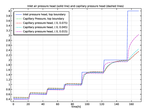
In the Settings window for 1D Plot Group, type Inlet air pressure and capillary pressure, air-water in the Label text field.
|
|
3
|
|
4
|
In the associated text field, type time[h].
|
|
5
|
|
6
|
In the Title text area, type Inlet air pressure head (solid line) and capillary pressure head (dashed lines).
|
|
7
|
|
1
|
|
3
|
|
4
|
|
5
|
|
6
|
|
8
|
|
1
|
|
2
|
In the Settings window for Point Graph, click Replace Expression in the upper-right corner of the y-Axis Data section. From the menu, choose Component 1 (comp1)>Definitions>Variables>Hc - Capillary pressure head - m.
|
|
3
|
Click to expand the Coloring and Style section. Find the Line style subsection. From the Line list, choose Dashed.
|
|
4
|
Locate the Legends section. In the table, enter the following settings:
|
|
5
|
|
1
|
|
2
|
|
3
|
|
4
|
Locate the Legends section. In the table, enter the following settings:
|
|
5
|
|
1
|
|
2
|
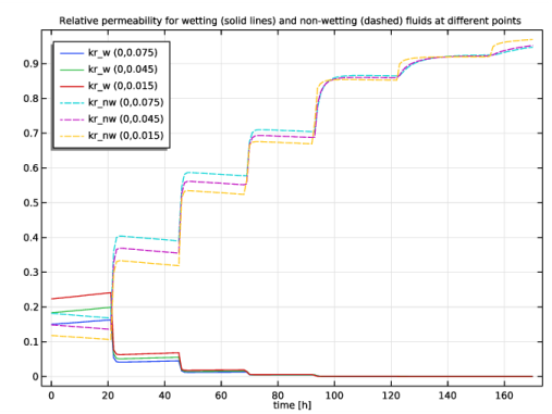
In the Settings window for 1D Plot Group, type Relative permeabilities at 3 points in the Label text field.
|
|
3
|
|
4
|
|
5
|
In the Title text area, type Relative permeability for wetting (solid lines) and non-wetting (dashed) fluids at different points.
|
|
6
|
|
7
|
In the associated text field, type time [h].
|
|
8
|
|
1
|
|
2
|
In the Settings window for Point Graph, click Replace Expression in the upper-right corner of the y-Axis Data section. From the menu, choose Component 1 (comp1)>Definitions>Variables>kr_w - Relative permeability, wetting phase.
|
|
3
|
|
4
|
|
1
|
|
2
|
In the Settings window for Point Graph, click Replace Expression in the upper-right corner of the y-Axis Data section. From the menu, choose Component 1 (comp1)>Definitions>Variables>kr_nw - Relative permeability, non-wetting phase.
|
|
3
|
Locate the Coloring and Style section. Find the Line style subsection. From the Line list, choose Dashed.
|
|
4
|
Locate the Legends section. In the table, enter the following settings:
|
|
5
|
|
1
|
|
2
|
|
3
|
|
1
|
|
2
|
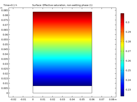
In the Settings window for Surface, click Replace Expression in the upper-right corner of the Expression section. From the menu, choose Component 1 (comp1)>Definitions>Variables>Se_nw - Effective saturation, non-wetting phase.
|
|
3
|
|
4
|
|
1
|
|
2
|
In the Settings window for 2D Plot Group, type Effective Saturation, non-wetting phase in the Label text field.
|
|
1
|
|
2
|
|
3
|
|
4
|
Browse to the model’s Application Libraries folder and double-click the file twophase_flow_column_air_oil.txt.
|
|
1
|
|
2
|
|
3
|
|
4
|
Browse to the model’s Application Libraries folder and double-click the file twophase_flow_column_oil_water.txt.
|
|
1
|
|
2
|
|
3
|
|
4
|
In the Physics and variables selection tree, select Component 1 (comp1)>Definitions>Air-oil experiment and Component 1 (comp1)>Definitions>Oil-water experiment.
|
|
5
|
Click
|
|
1
|
|
2
|
|
3
|
|
4
|
|
5
|
|
1
|
|
2
|
|
3
|
|
1
|
|
2
|
|
3
|
|
4
|
|
5
|
Locate the Physics and Variables Selection section. Select the Modify model configuration for study step check box.
|
|
6
|
In the Physics and variables selection tree, select Component 1 (comp1)>Definitions>Air-water experiment and Component 1 (comp1)>Definitions>Oil-water experiment.
|
|
7
|
Click
|
|
8
|
|
1
|
In the Model Builder window, under Results>Datasets right-click Cut Point 2D 1 and choose Duplicate.
|
|
2
|
|
3
|
|
1
|
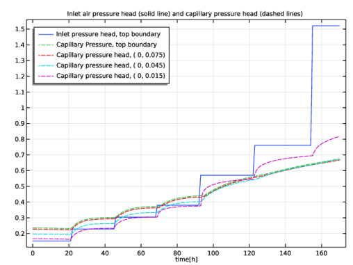
In the Model Builder window, right-click Inlet air pressure and capillary pressure, air-water and choose Duplicate.
|
|
2
|
In the Settings window for 1D Plot Group, type Inlet air pressure and capillary pressure, air-oil in the Label text field.
|
|
3
|
|
1
|
In the Model Builder window, expand the Inlet air pressure and capillary pressure, air-oil node, then click Point Graph 1.
|
|
2
|
|
3
|
|
1
|
|
2
|
|
3
|
|
4
|
|
1
|
|
2
|
|
3
|
|
4
|
|
5
|
|
1
|
|
2
|
|
3
|
|
1
|
|
2
|
|
3
|
|
4
|
|
5
|
Locate the Physics and Variables Selection section. Select the Modify model configuration for study step check box.
|
|
6
|
In the Physics and variables selection tree, select Component 1 (comp1)>Definitions>Air-water experiment and Component 1 (comp1)>Definitions>Air-oil experiment.
|
|
7
|
Click
|
|
8
|
|
1
|
In the Model Builder window, under Results>Datasets right-click Cut Point 2D 2 and choose Duplicate.
|
|
2
|
|
3
|
|
1
|
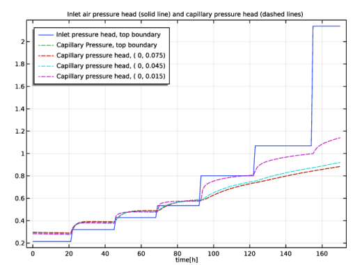
In the Model Builder window, right-click Inlet air pressure and capillary pressure, air-oil and choose Duplicate.
|
|
2
|
In the Settings window for 1D Plot Group, type Inlet air pressure and capillary pressure, oil-water in the Label text field.
|
|
3
|
|
1
|
In the Model Builder window, expand the Inlet air pressure and capillary pressure, oil-water node, then click Point Graph 3.
|
|
2
|
|
3
|
|
4
|