PDF

Geothermal Doublet
Introduction
The use of geothermal energy has become an important topic worldwide, not only sparked by the debate on climate change. Particularly in regions with lower geothermal energy, the requirements for geothermal plants are high in order to ensure a continuous and long-term energy supply.
This example of a hydrothermal doublet studies the coupled porous media flow and heat transfer problem using the Darcy’s Law and Heat Transfer in Porous Media interfaces. It shows how to set up a system of a layered subsurface with different geological and thermal properties including fractures and the injection and production side of a doublet.
Model Definition
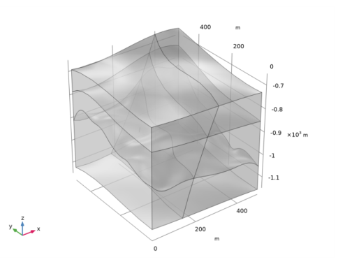
The model geometry (Figure 1) consists of three geological layers ranged by a fault zone. The layers, their elevation, and the fault zone are interpolation functions from an artificial dataset. Different hydraulic and thermal properties are defined for the layers. The evolution of the flow and temperature field over 10 years is studied.
Figure 1: Geometry of the model including three geologic layers, fracture, and the doublet’s production and injection side (edges).
Fluid Flow
The flow in the fracture is in general much faster than in the surrounding porous matrix. The cubic law is a common correlation for modeling fracture flow. It defines the permeability κf (m2) in the fracture according to
where df (m) is the fracture’s aperture and ff the roughness factor. With this definition, the name cubic law results from the definition of the fracture’s transmissivity
.
A hydraulic gradient in x direction is applied as boundary condition on the vertical boundaries. Top and bottom boundary are defined as impermeable. Two edges represent the geothermal doublet injection and production side. Injection and pumping is modeled using the Well feature. Water injection is defined using the mass flow rate option with M0 = ρW·120 l/s.
Heat Transfer
An initial geothermal gradient of 0.03 K/m is applied. The vertical boundaries are defined as open boundaries. This means that a temperature condition using the same geothermal gradient is active if n · u < 0 (inflow) or otherwise n · q = 0 (outflow). Analogously to the Fracture Flow boundary condition in the Darcy’s Law interface, the heat transfer in the fracture is modeled using the fracture boundary condition of the heat transfer interface.
To model the heat source term caused by the injection well, a line heat source feature is applied according to
where Cp (J/(kg·K)) is the water heat capacity, l the well length, Tinj = 278 K the injection temperature, and T the current temperature.
Results and Discussion
The pressure field is shown in Figure 2.
Figure 2: Pressure distribution after 10 years.
Figure 3 shows the temperature distribution in the fracture together with streamlines that visualize the flow field, showing the flow from the injection to the production side of the doublet.
Figure 3: Temperature distribution in the fracture and streamlines for the Darcy velocity field after 10 years.
It is interesting to evaluate the production temperature over time. As shown in Figure 4, the production temperature decreases about 20 K over 10 years. This indicates that the doublet at the operating conditions will not provide a stable long term energy supply and that a different configurations should be tested. This can be done by varying one or more of the parameters in the model to see which setup is more appropriate.
Figure 4: Production temperature over 10 years.
Application Library path: Subsurface_Flow_Module/Heat_Transfer/geothermal_doublet
Modeling Instructions
From the File menu, choose New.
New
In the New window, click  Model Wizard.
Model Wizard
1
In the Model Wizard window, click  3D.
2
In the Select Physics tree, select Fluid Flow>Porous Media and Subsurface Flow>Darcy’s Law (dl).
3
Click Add.
4
In the Select Physics tree, select Heat Transfer>Heat Transfer in Porous Media (ht).
5
Click Add.
6
Root
Start with loading the parameterized geometry sequence into the model.
Geometry 1
1
In the Geometry toolbar, click  Insert Sequence.
2
3
In the Geometry toolbar, click  Build All.
4
Click the  Go to Default View button in the Graphics toolbar.
The geometry parameters that are used were added to the Parameters list automatically. Add a few more parameters that are used to set up the physics interfaces.
Global Definitions
Parameters 1
1
In the Model Builder window, under Global Definitions click Parameters 1.
2
In the Settings window for Parameters, locate the Parameters section.
3
Selections help to improve the whole modeling process. Define them now and use them later where needed.
Definitions
Injection well
1
In the Model Builder window, expand the Component 1 (comp1)>Definitions node.
2
Right-click Definitions and choose Selections>Explicit.
3
In the Settings window for Explicit, locate the Input Entities section.
4
From the Geometric entity level list, choose Edge.
5
Click the  Wireframe Rendering button in the Graphics toolbar.
6
7
In the Label text field, type Injection well.
Production well
1
In the Definitions toolbar, click  Explicit.
2
In the Settings window for Explicit, locate the Input Entities section.
3
From the Geometric entity level list, choose Edge.
4
5
In the Label text field, type Production well.
Top layer
1
In the Definitions toolbar, click  Explicit.
2
3
In the Settings window for Explicit, type Top layer in the Label text field.
Middle layer
1
In the Definitions toolbar, click  Explicit.
2
3
In the Settings window for Explicit, type Middle layer in the Label text field.
Bottom layer
1
In the Definitions toolbar, click  Explicit.
2
3
In the Settings window for Explicit, type Bottom layer in the Label text field.
Fracture
1
In the Definitions toolbar, click  Explicit.
2
In the Settings window for Explicit, locate the Input Entities section.
3
From the Geometric entity level list, choose Boundary.
4
5
Select the Group by continuous tangent check box.
6
In the Label text field, type Fracture.
Outer boundaries
1
In the Definitions toolbar, click  Explicit.
2
In the Settings window for Explicit, locate the Input Entities section.
3
From the Geometric entity level list, choose Boundary.
4
5
Select the Group by continuous tangent check box.
6
7
In the Label text field, type Outer boundaries.
Add materials to the materials node, but do not define their properties at this point. After setting up the physics interface COMSOL Multiphysics automatically detects which material properties are needed.
Materials
Top Layer
1
In the Model Builder window, under Component 1 (comp1) right-click Materials and choose Blank Material.
2
In the Settings window for Material, type Top Layer in the Label text field.
Middle layer
1
Right-click Materials and choose Blank Material.
2
In the Settings window for Material, type Middle layer in the Label text field.
3
Locate the Geometric Entity Selection section. From the Selection list, choose Middle layer.
Bottom layer
1
Right-click Materials and choose Blank Material.
2
In the Settings window for Material, type Bottom layer in the Label text field.
3
Locate the Geometric Entity Selection section. From the Selection list, choose Bottom layer.
Fracture
1
Right-click Materials and choose Blank Material.
2
In the Settings window for Material, type Fracture in the Label text field.
3
Locate the Geometric Entity Selection section. From the Geometric entity level list, choose Boundary.
4
From the Selection list, choose Fracture.
Add Material
1
In the Home toolbar, click  Add Material to open the Add Material window.
2
Go to the Add Material window.
3
In the tree, select Built-in>Water, liquid.
4
Click Add to Component in the window toolbar.
5
In the Home toolbar, click  Add Material to close the Add Material window.
Darcy’s Law (dl)
Now, set up the physics interfaces.
Fluid and Matrix Properties 1
1
In the Model Builder window, under Component 1 (comp1)>Darcy’s Law (dl) click Fluid and Matrix Properties 1.
2
In the Settings window for Fluid and Matrix Properties, locate the Fluid Properties section.
3
From the Fluid material list, choose Water, liquid (mat5).
Fracture Flow 1
1
In the Physics toolbar, click  Boundaries and choose Fracture Flow.
2
In the Settings window for Fracture Flow, locate the Boundary Selection section.
3
From the Selection list, choose Fracture.
Fluid and Fracture Properties 1
1
In the Model Builder window, expand the Fracture Flow 1 node, then click Fluid and Fracture Properties 1.
2
In the Settings window for Fluid and Fracture Properties, locate the Fluid Properties section.
3
From the Fluid material list, choose Water, liquid (mat5).
4
Locate the Fracture Properties section. From the Permeability model list, choose Cubic law.
5
In the ff text field, type f_f.
Aperture 1
1
In the Model Builder window, click Aperture 1.
2
In the Settings window for Aperture, locate the Aperture section.
3
In the df text field, type d_f.
Hydraulic Head 1
1
In the Physics toolbar, click  Boundaries and choose Hydraulic Head.
2
In the Settings window for Hydraulic Head, locate the Boundary Selection section.
3
From the Selection list, choose Outer boundaries.
4
Locate the Hydraulic Head section. In the H0 text field, type -deltaH*x.
Use the Well feature to define the injection and production side of the doublet.
Well 1
1
In the Physics toolbar, click  Edges and choose Well.
2
In the Settings window for Well, locate the Edge Selection section.
3
From the Selection list, choose Injection well.
4
Locate the Well section. In the dw text field, type 2*r_bore.
5
From the Specify list, choose Mass flow.
6
Locate the Mass Flow section. In the M0 text field, type pump*dl.rho.
The expression dl.rho refers to the water density that is defined by Darcy’s Law interface.
Well 2
1
In the Physics toolbar, click  Edges and choose Well.
2
In the Settings window for Well, locate the Edge Selection section.
3
From the Selection list, choose Production well.
4
Locate the Well section. In the dw text field, type 2*r_bore.
5
From the Well type list, choose Production.
6
From the Specify list, choose Mass flow.
7
Locate the Mass Flow section. In the M0 text field, type pump*dl.rho.
Heat Transfer in Porous Media (ht)
Fluid 1
1
In the Model Builder window, under Component 1 (comp1)>Heat Transfer in Porous Media (ht)>Porous Medium 1 click Fluid 1.
2
In the Settings window for Fluid, locate the Heat Convection section.
3
From the u list, choose Darcy’s velocity field (dl).
4
Locate the Heat Conduction, Fluid section. From the kf list, choose User defined. In the associated text field, type mat5.def.k(T).
5
Locate the Thermodynamics, Fluid section. From the ρf list, choose User defined. In the associated text field, type mat5.def.rho(T).
6
From the Cp,f list, choose User defined. In the associated text field, type mat5.def.Cp(T).
7
From the γ list, choose User defined. In the associated text field, type mat5.def.gamma_w(T).
Porous Matrix 1
1
In the Model Builder window, click Porous Matrix 1.
2
In the Settings window for Porous Matrix, locate the Matrix Properties section.
3
From the Define list, choose Solid phase properties.
Initial Values 1
Define the geothermal gradient as initial values.
1
In the Model Builder window, click Initial Values 1.
2
In the Settings window for Initial Values, locate the Initial Values section.
3
In the T text field, type T_top-0.03[K/m]*z.
Open Boundary 1
1
In the Physics toolbar, click  Boundaries and choose Open Boundary.
2
In the Settings window for Open Boundary, locate the Boundary Selection section.
3
From the Selection list, choose Outer boundaries.
4
Locate the Upstream Properties section. In the Tustr text field, type T_top-delta_Tz*z.
Fracture 1
1
In the Physics toolbar, click  Boundaries and choose Fracture.
2
In the Settings window for Fracture, locate the Boundary Selection section.
3
From the Selection list, choose Fracture.
4
Locate the Shell Properties section. From the Shell type list, choose Nonlayered shell. In the Lth text field, type d_f.
5
Locate the Fluid Material section. From the list, choose Water, liquid (mat5).
6
Locate the Heat Convection section. From the u list, choose Darcy’s velocity field (dl).
7
Locate the Porous Material section. From the θp list, choose Volume fraction (dl/ff1/dlm1).
8
Locate the Heat Conduction, Porous Matrix section. From the kp list, choose User defined. In the associated text field, type 3.
9
Locate the Thermodynamics, Porous Matrix section. From the ρp list, choose User defined. In the associated text field, type 1.2e3.
10
From the Cp,p list, choose User defined. In the associated text field, type 800.
Line Heat Source 1
1
In the Physics toolbar, click  Edges and choose Line Heat Source.
2
In the Settings window for Line Heat Source, locate the Edge Selection section.
3
From the Selection list, choose Injection well.
4
Locate the Line Heat Source section. In the Ql text field, type mat5.def.Cp*dl.well1.Ml*(T_inj-T).
5
Locate the Heat Source Radius section. Select the Specify heat source radius check box.
6
In the R text field, type r_bore.
Materials
Now you can define the material properties.
Top Layer (mat1)
1
In the Model Builder window, under Component 1 (comp1)>Materials click Top Layer (mat1).
2
In the Settings window for Material, locate the Material Contents section.
3
Middle layer (mat2)
1
In the Model Builder window, click Middle layer (mat2).
2
In the Settings window for Material, locate the Material Contents section.
3
Bottom layer (mat3)
1
In the Model Builder window, click Bottom layer (mat3).
2
In the Settings window for Material, locate the Material Contents section.
3
Fracture (mat4)
1
In the Model Builder window, click Fracture (mat4).
2
In the Settings window for Material, locate the Material Contents section.
3
Mesh 1
Adjust the default mesh settings slightly to make sure, that the injection and production well are resolved properly.
1
In the Model Builder window, under Component 1 (comp1) click Mesh 1.
2
In the Settings window for Mesh, locate the Physics-Controlled Mesh section.
3
From the Element size list, choose Fine.
4
Locate the Mesh Settings section. From the Sequence type list, choose User-controlled mesh.
Size 1
1
In the Model Builder window, right-click Free Tetrahedral 1 and choose Size.
2
In the Settings window for Size, locate the Geometric Entity Selection section.
3
From the Geometric entity level list, choose Edge.
4
5
Locate the Element Size section. From the Predefined list, choose Extra fine.
6
Click the Custom button.
7
Locate the Element Size Parameters section. Select the Maximum element size check box.
8
9
Click  Build All.
Add Study
1
In the Home toolbar, click  Add Study to open the Add Study window.
2
Go to the Add Study window.
3
Find the Studies subsection. In the Select Study tree, select General Studies>Stationary.
4
Find the Physics interfaces in study subsection. In the table, clear the Solve check box for Heat Transfer in Porous Media (ht).
5
Click Add Study in the window toolbar.
6
In the Home toolbar, click  Add Study to close the Add Study window.
Study 1
Step 1: Stationary
1
In the Settings window for Stationary, locate the Physics and Variables Selection section.
2
Select the Modify model configuration for study step check box.
3
In the Physics and variables selection tree, select Component 1 (comp1)>Darcy’s Law (dl)>Well 1 and Component 1 (comp1)>Darcy’s Law (dl)>Well 2.
4
Click  Disable.
This first stationary step results in a groundwater flow field which serves as a starting point for the subsequent time dependent analysis of the performance of the geothermal doublet.
Time Dependent
1
In the Study toolbar, click  Study Steps and choose Time Dependent>Time Dependent.
2
In the Settings window for Time Dependent, locate the Study Settings section.
3
From the Time unit list, choose a.
4
In the Output times text field, type range(0,0.2,10).
Solution 1 (sol1)
1
In the Study toolbar, click  Show Default Solver.
2
In the Model Builder window, expand the Solution 1 (sol1) node, then click Time-Dependent Solver 1.
3
In the Settings window for Time-Dependent Solver, click to expand the Time Stepping section.
4
From the Maximum step constraint list, choose Constant.
Constraining the maximum time step ensures that the transient behavior of the whole system is resolved properly.
5
In the Study toolbar, click  Compute.
Results
COMSOL Multiphysics automatically creates four default plots. Modify the pressure plot to create Figure 2.
Selection 1
1
In the Model Builder window, expand the Results>Pressure (dl) node.
2
Right-click Surface and choose Selection.
3
In the Settings window for Selection, locate the Selection section.
4
From the Selection list, choose All boundaries, and remove the top and front boundaries, which corresponds to:
5
6
In the Pressure (dl) toolbar, click  Plot.
Cut Plane 1
Create the plot in Figure 3 as follows:
1
In the Results toolbar, click  Cut Plane.
2
In the Settings window for Cut Plane, locate the Plane Data section.
3
From the Plane list, choose XY-planes.
4
In the Z-coordinate text field, type -880.
Cut Plane 2
1
In the Results toolbar, click  Cut Plane.
2
In the Settings window for Cut Plane, locate the Plane Data section.
3
From the Plane list, choose ZX-planes.
4
In the Y-coordinate text field, type 250.
Temperature and Flow Field
1
In the Results toolbar, click  3D Plot Group.
2
In the Settings window for 3D Plot Group, type Temperature and Flow Field in the Label text field.
Surface 1
1
Right-click Temperature and Flow Field and choose Surface.
2
In the Settings window for Surface, locate the Expression section.
3
In the Expression text field, type 1.
4
Locate the Coloring and Style section. From the Color table list, choose GrayScale.
5
Locate the Expression section. In the Expression text field, type z.
6
Locate the Coloring and Style section. Clear the Color legend check box.
Selection 1
1
Right-click Surface 1 and choose Selection.
2
In the Settings window for Selection, locate the Selection section.
3
From the Selection list, choose Outer boundaries.
Modify this selection to obtain the figure below. This corresponds to the following step:
4
Surface 2
1
In the Model Builder window, right-click Temperature and Flow Field and choose Surface.
2
In the Settings window for Surface, locate the Expression section.
3
In the Expression text field, type T.
4
Locate the Coloring and Style section. From the Color table list, choose ThermalLight.
Selection 1
1
Right-click Surface 2 and choose Selection.
2
In the Settings window for Selection, locate the Selection section.
3
From the Selection list, choose Fracture.
Temperature and Flow Field
In the Model Builder window, click Temperature and Flow Field.
Streamline Surface 1
1
In the Temperature and Flow Field toolbar, click  More Plots and choose Streamline Surface.
2
In the Settings window for Streamline Surface, locate the Data section.
3
From the Dataset list, choose Cut Plane 1.
4
From the Solution parameters list, choose From parent.
5
Locate the Streamline Positioning section. In the Points text field, type 30.
Color Expression 1
Right-click Streamline Surface 1 and choose Color Expression.
Streamline Surface 2
1
In the Model Builder window, under Results>Temperature and Flow Field right-click Streamline Surface 1 and choose Duplicate.
2
In the Settings window for Streamline Surface, locate the Data section.
3
From the Dataset list, choose Cut Plane 2.
4
Click to expand the Inherit Style section. From the Plot list, choose Streamline Surface 1.
5
In the Temperature and Flow Field toolbar, click  Plot.
6
Click the  Zoom Extents button in the Graphics toolbar.
Evaluate the production temperature and compare with Figure 4.
Line Average 1
1
In the Results toolbar, click  More Derived Values and choose Average>Line Average.
2
3
In the Settings window for Line Average, click  Evaluate.
Table
1
Go to the Table window.
2
Click Table Graph in the window toolbar.
Results
Production Temperature
1
In the Model Builder window, under Results click 1D Plot Group 6.
2
In the Settings window for 1D Plot Group, type Production Temperature in the Label text field.