PDF

Scordelis–Lo Roof Shell Benchmark
Introduction
In the following example you build and solve a 3D shell model using the Shell interface. This example is a widely used benchmark model called the Scordelis–Lo roof. The computed maximum z-deformation is compared with the value given in Ref. 1.
Model Definition
GEOMETRY
The geometry consists of a curved face as shown in Figure 1. Only one quarter is analyzed due to symmetry.
Figure 1: The Scordelis-Lo roof shell benchmark geometry.
Roof length 2L = 50 m
Roof radius R = 25 m.
Material
Constraints
Load
A force per area unit of 90 N/m2 in the z direction is applied on the surface.
Results and Discussion
The maximum deformation in the global z direction with the default mesh settings is shown in Figure 2. The computed value is 0.303 m.
Figure 2: z-displacement with 176 triangular elements.
When changing to a mapped mesh, the more efficient quadrilateral elements are used. The result is 0.301 m as shown in Figure 3. With a very fine mesh, the value converges to 0.302 m, Figure 4. The reference solution quoted in Ref. 1 for the midside vertical displacement is 0.3086 m. The value 0.302 m is in fact observed in other published benchmark results treating this problem as the value that this problem converges toward. A summary of the performance for different element types and mesh densities is given in Table 1. As can be seen, the results are good even with rather coarse meshes.
Figure 3: z-displacement with 70 quadrilateral elements.
Figure 4: z-displacement with 580 quadrilateral elements.
Reference
1. R.H. MacNeal and R.L. Harder, Proposed Standard Set of Problems to Test Finite Element Accuracy, Finite Elements in Analysis and Design, 1, 1985.
Application Library path: Structural_Mechanics_Module/Verification_Examples/scordelis_lo_roof
Modeling Instructions
From the File menu, choose New.
New
In the New window, click  Model Wizard.
Model Wizard
1
In the Model Wizard window, click  3D.
2
In the Select Physics tree, select Structural Mechanics>Shell (shell).
3
Click Add.
4
Click  Study.
5
In the Select Study tree, select General Studies>Stationary.
6
Geometry 1
Work Plane 1 (wp1)
1
In the Geometry toolbar, click  Work Plane.
2
In the Settings window for Work Plane, click  Show Work Plane.
Work Plane 1 (wp1)>Plane Geometry
In the Model Builder window, click Plane Geometry.
Work Plane 1 (wp1)>Polygon 1 (pol1)
1
In the Work Plane toolbar, click  Polygon.
2
In the Settings window for Polygon, locate the Coordinates section.
3
4
Right-click Polygon 1 (pol1) and choose Build All Objects.
Revolve 1 (rev1)
1
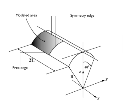
In the Model Builder window, under Component 1 (comp1)>Geometry 1 right-click Work Plane 1 (wp1) and choose Revolve.
2
In the Settings window for Revolve, locate the Revolution Angles section.
3
Click the Angles button.
4
In the Start angle text field, type 90.
5
In the End angle text field, type 90+40.
6
Locate the Revolution Axis section. Find the Direction of revolution axis subsection. In the xw text field, type 1.
7
In the yw text field, type 0.
8
Click  Build Selected.
9
Click the  Zoom Extents button in the Graphics toolbar.
Form Union (fin)
1
In the Model Builder window, click Form Union (fin).
2
In the Settings window for Form Union/Assembly, click  Build Selected.
Shell (shell)
Thickness and Offset 1
1
In the Model Builder window, under Component 1 (comp1)>Shell (shell) click Thickness and Offset 1.
2
In the Settings window for Thickness and Offset, locate the Thickness and Offset section.
3
In the d text field, type 0.25.
Symmetry 1
1
In the Physics toolbar, click  Edges and choose Symmetry.
2
Prescribed Displacement/Rotation 1
1
In the Physics toolbar, click  Edges and choose Prescribed Displacement/Rotation.
2
3
In the Settings window for Prescribed Displacement/Rotation, locate the Prescribed Displacement section.
4
Select the Prescribed in y direction check box.
5
Select the Prescribed in z direction check box.
Face Load 1
1
In the Physics toolbar, click  Boundaries and choose Face Load.
2
3
In the Settings window for Face Load, locate the Force section.
4
Specify the FA vector as
Materials
Material 1 (mat1)
1
In the Model Builder window, under Component 1 (comp1) right-click Materials and choose Blank Material.
2
In the Settings window for Material, locate the Material Contents section.
3
Mesh 1
First, compute the results with the default triangular mesh.
Free Triangular 1
1
In the Mesh toolbar, click  Boundary and choose Free Triangular.
2
In the Settings window for Free Triangular, locate the Boundary Selection section.
3
From the Selection list, choose All boundaries.
4
Click  Build All.
Study 1: Tri Normal
1
In the Model Builder window, click Study 1.
2
In the Settings window for Study, type Study 1: Tri Normal in the Label text field.
3
In the Home toolbar, click  Compute.
Results
Vertical displacement
1
In the Settings window for 3D Plot Group, type Vertical displacement in the Label text field.
2
Click the  Zoom Extents button in the Graphics toolbar.
Surface 1
1
In the Model Builder window, expand the Vertical displacement node, then click Surface 1.
2
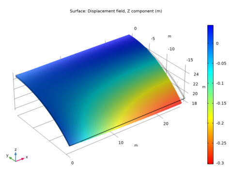
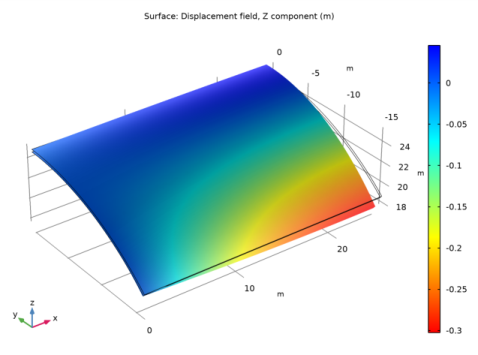
In the Settings window for Surface, click Replace Expression in the upper-right corner of the Expression section. From the menu, choose Component 1 (comp1)>Shell>Displacement>Displacement field - m>w - Displacement field, Z component.
3
Locate the Coloring and Style section. Select the Reverse color table check box.
Vertical displacement
1
In the Model Builder window, click Vertical displacement.
2
In the Vertical displacement toolbar, click  Plot.
Tri Normal
1
In the Model Builder window, expand the Results>Datasets node, then click Study 1: Tri Normal/Solution 1 (sol1).
2
In the Settings window for Solution, type Tri Normal in the Label text field.
Switch to the more effective quadrilateral mesh elements.
Tri Normal
1
In the Model Builder window, under Component 1 (comp1) click Mesh 1.
2
In the Settings window for Mesh, type Tri Normal in the Label text field.
Quad Normal
1
In the Mesh toolbar, click  Add Mesh.
2
In the Settings window for Mesh, type Quad Normal in the Label text field.
Mapped 1
1
In the Mesh toolbar, click  Boundary and choose Mapped.
2
In the Settings window for Mapped, locate the Boundary Selection section.
3
From the Geometric entity level list, choose Remaining.
4
Click  Build All.
Add Study
1
In the Home toolbar, click  Add Study to open the Add Study window.
2
Go to the Add Study window.
3
Find the Studies subsection. In the Select Study tree, select General Studies>Stationary.
4
Click Add Study in the window toolbar.
5
In the Home toolbar, click  Add Study to close the Add Study window.
Study 2: Quad Normal
1
In the Model Builder window, click Study 2.
2
In the Settings window for Study, type Study 2: Quad Normal in the Label text field.
3
Locate the Study Settings section. Clear the Generate default plots check box.
4
In the Home toolbar, click  Compute.
Results
Vertical displacement
1
In the Model Builder window, under Results click Vertical displacement.
2
In the Settings window for 3D Plot Group, locate the Data section.
3
From the Dataset list, choose Study 2: Quad Normal/Solution 2 (sol2).
4
In the Vertical displacement toolbar, click  Plot.
Quad Normal
1
In the Model Builder window, under Results>Datasets click Study 2: Quad Normal/Solution 2 (sol2).
2
In the Settings window for Solution, type Quad Normal in the Label text field.
Examine a well converged result with a fine quadrilateral mesh.
Quad Normal
In the Model Builder window, under Component 1 (comp1)>Meshes right-click Quad Normal and choose Duplicate.
Quad Extra fine
In the Settings window for Mesh, type Quad Extra fine in the Label text field.
Size
1
In the Model Builder window, expand the Quad Extra fine node, then click Size.
2
In the Settings window for Size, locate the Element Size section.
3
From the Predefined list, choose Extra fine.
4
Click  Build All.
Add Study
1
In the Home toolbar, click  Add Study to open the Add Study window.
2
Go to the Add Study window.
3
Find the Studies subsection. In the Select Study tree, select General Studies>Stationary.
4
Click Add Study in the window toolbar.
5
In the Home toolbar, click  Add Study to close the Add Study window.
Study 3: Quad Extra fine
1
In the Model Builder window, click Study 3.
2
In the Settings window for Study, type Study 3: Quad Extra fine in the Label text field.
3
Locate the Study Settings section. Clear the Generate default plots check box.
4
In the Home toolbar, click  Compute.
Results
Vertical displacement
1
In the Model Builder window, under Results click Vertical displacement.
2
In the Settings window for 3D Plot Group, locate the Data section.
3
From the Dataset list, choose Study 3: Quad Extra fine/Solution 3 (sol3).
4
In the Vertical displacement toolbar, click  Plot.
Quad Extra fine
1
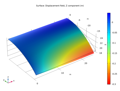
In the Model Builder window, under Results>Datasets click Study 3: Quad Extra fine/Solution 3 (sol3).
2
In the Settings window for Solution, type Quad Extra fine in the Label text field.
Examine a well converged result with a triangular mesh.
Tri Normal
In the Model Builder window, under Component 1 (comp1)>Meshes right-click Tri Normal and choose Duplicate.
Tri Extra Fine
In the Settings window for Mesh, type Tri Extra Fine in the Label text field.
Size
1
In the Model Builder window, expand the Tri Extra Fine node, then click Size.
2
In the Settings window for Size, locate the Element Size section.
3
From the Predefined list, choose Extra fine.
4
Click  Build All.
Add Study
1
In the Home toolbar, click  Add Study to open the Add Study window.
2
Go to the Add Study window.
3
Find the Studies subsection. In the Select Study tree, select General Studies>Stationary.
4
Click Add Study in the window toolbar.
5
In the Home toolbar, click  Add Study to close the Add Study window.
Study 4: Tri Extra fine
1
In the Model Builder window, click Study 4.
2
In the Settings window for Study, type Study 4: Tri Extra fine in the Label text field.
3
Locate the Study Settings section. Clear the Generate default plots check box.
4
In the Home toolbar, click  Compute.
Results
Vertical displacement
1
In the Model Builder window, under Results click Vertical displacement.
2
In the Settings window for 3D Plot Group, locate the Data section.
3
From the Dataset list, choose Study 4: Tri Extra fine/Solution 4 (sol4).
4
In the Vertical displacement toolbar, click  Plot.
Tri Extra fine
1
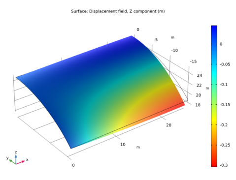
In the Model Builder window, under Results>Datasets click Study 4: Tri Extra fine/Solution 4 (sol4).
2
In the Settings window for Solution, type Tri Extra fine in the Label text field.
Investigate how well the elements perform with a very coarse mesh.
Tri Normal
In the Model Builder window, under Component 1 (comp1)>Meshes right-click Tri Normal and choose Duplicate.
Tri Coarser
In the Settings window for Mesh, type Tri Coarser in the Label text field.
Size
1
In the Model Builder window, expand the Tri Coarser node, then click Size.
2
In the Settings window for Size, locate the Element Size section.
3
From the Predefined list, choose Coarser.
4
Click  Build All.
Add Study
1
In the Home toolbar, click  Add Study to open the Add Study window.
2
Go to the Add Study window.
3
Find the Studies subsection. In the Select Study tree, select General Studies>Stationary.
4
Click Add Study in the window toolbar.
5
In the Home toolbar, click  Add Study to close the Add Study window.
Study 5: Tri Coarser
1
In the Model Builder window, click Study 5.
2
In the Settings window for Study, type Study 5: Tri Coarser in the Label text field.
3
Locate the Study Settings section. Clear the Generate default plots check box.
4
In the Home toolbar, click  Compute.
Results
Vertical displacement
1
In the Model Builder window, under Results click Vertical displacement.
2
In the Settings window for 3D Plot Group, locate the Data section.
3
From the Dataset list, choose Study 5: Tri Coarser/Solution 5 (sol5).
4
In the Vertical displacement toolbar, click  Plot.
Tri Coarser
1
In the Model Builder window, under Results>Datasets click Study 5: Tri Coarser/Solution 5 (sol5).
2
In the Settings window for Solution, type Tri Coarser in the Label text field.
Quad Normal
In the Model Builder window, under Component 1 (comp1)>Meshes right-click Quad Normal and choose Duplicate.
Quad Coarser
In the Settings window for Mesh, type Quad Coarser in the Label text field.
Size
1
In the Model Builder window, expand the Quad Coarser node, then click Size.
2
In the Settings window for Size, locate the Element Size section.
3
From the Predefined list, choose Coarser.
Add Study
1
In the Home toolbar, click  Add Study to open the Add Study window.
2
Go to the Add Study window.
3
Find the Studies subsection. In the Select Study tree, select General Studies>Stationary.
4
Click Add Study in the window toolbar.
5
In the Home toolbar, click  Add Study to close the Add Study window.
Study 6: Quad Coarser
1
In the Model Builder window, click Study 6.
2
In the Settings window for Study, type Study 6: Quad Coarser in the Label text field.
3
Locate the Study Settings section. Clear the Generate default plots check box.
4
In the Home toolbar, click  Compute.
Results
Vertical displacement
1
In the Model Builder window, under Results click Vertical displacement.
2
In the Settings window for 3D Plot Group, locate the Data section.
3
From the Dataset list, choose Study 6: Quad Coarser/Solution 6 (sol6).
4
In the Vertical displacement toolbar, click  Plot.
Quad Coarser
1
In the Model Builder window, under Results>Datasets click Study 6: Quad Coarser/Solution 6 (sol6).
2
In the Settings window for Solution, type Quad Coarser in the Label text field.
The following section compares the maximum deformation of the midpoint, in the vertical direction, for different element types and mesh densities.
Point Evaluation 1
1
In the Results toolbar, click  Point Evaluation.
2
3
In the Settings window for Point Evaluation, locate the Expressions section.
4
5
Click  Evaluate.
Point Evaluation 2
1
Right-click Point Evaluation 1 and choose Duplicate.
2
In the Settings window for Point Evaluation, locate the Data section.
3
From the Dataset list, choose Quad Normal (sol2).
4
Locate the Expressions section. In the table, enter the following settings:
5
Click  Evaluate (Table 1 - Point Evaluation 1).
Point Evaluation 3
1
Right-click Point Evaluation 2 and choose Duplicate.
2
In the Settings window for Point Evaluation, locate the Data section.
3
From the Dataset list, choose Quad Extra fine (sol3).
4
Locate the Expressions section. In the table, enter the following settings:
5
Click  Evaluate (Table 1 - Point Evaluation 1).
Point Evaluation 4
1
Right-click Point Evaluation 3 and choose Duplicate.
2
In the Settings window for Point Evaluation, locate the Data section.
3
From the Dataset list, choose Tri Extra fine (sol4).
4
Locate the Expressions section. In the table, enter the following settings:
5
Click  Evaluate (Table 1 - Point Evaluation 1).
Point Evaluation 5
1
Right-click Point Evaluation 4 and choose Duplicate.
2
In the Settings window for Point Evaluation, locate the Data section.
3
From the Dataset list, choose Tri Coarser (sol5).
4
Locate the Expressions section. In the table, enter the following settings:
5
Click  Evaluate (Table 1 - Point Evaluation 1).
Point Evaluation 6
1
Right-click Point Evaluation 5 and choose Duplicate.
2
In the Settings window for Point Evaluation, locate the Data section.
3
From the Dataset list, choose Quad Coarser (sol6).
4
Locate the Expressions section. In the table, enter the following settings:
5
Click  Evaluate (Table 1 - Point Evaluation 1).