PDF

Eigenfrequency Analysis of a Free Cylinder
Introduction
In the following example you compute the eigenfrequencies of a free circular pipe using three different approaches:
The example is taken from NAFEMS Free Vibration Benchmarks (Ref. 1). The eigenfrequencies are compared with the values given in the benchmark report.
As an extension, you will also compute eigenfrequencies with twisting deformation.
Model Definition
The model is NAFEMS Test No 41, “Free Cylinder” described on page 41 in NAFEMS Free Vibration Benchmarks, vol. 3 (Ref. 1). The Benchmark tests the capability to handle rigid body modes and eigenfrequencies.
The cylinder is 10 m tall with an inner radius of 1.8 m and a thickness of 0.4 m.
Figure 1: Model geometry in the rz-plane.
In the axisymmetric solid model, the geometry consists of this rectangle.
In the axisymmetric shell interface, the mesh is placed on the line representing the inner boundary of the cylinder, and an offset property is used in order to account for the fact that the shell model should represent the midsurface.
In the 3D solid model, the rectangle is swept around the axis of revolution, so that a 15° sector is formed. As long as 360° is as an exact multiple of the sector angle, any angle could have been used.
Material
The material is isotropic linear elastic with E = 2.0·1011 Pa, ν = 0.3, and ρ = 8000 kg/m3.
Loads
In an eigenfrequency analysis loads are not needed.
Constraints
In the axisymmetric models, no constraints are applied because the cylinder is free. In the 3D solid model, cyclic symmetry constraints are applied to the cuts in the azimuthal direction.
Results
For structural mechanics, there are two possible interpretations of axisymmetry. The most common one is that there are no displacements out of the RZ-plane. Another interpretation, which also allows twisting motion, is that all derivatives of the displacements with respect to the azimuthal coordinate is zero. Such an extension is available when using the Solid Mechanics interface.
The original NAFEMS example does not contain out-of-plane displacements, in which case there is one rigid body mode. The rigid body mode with an eigenvalue close to zero is found in all physics interfaces. The corresponding shape is a pure axial rigid body translation without any radial displacement. The eigenfrequencies are in close agreement with the target values from the NAFEMS Free Vibration Benchmarks (Ref. 1); see below.
f2
f3
f4
f5
f6
The analytical solution for twisting vibration of a free cylindrical pipe is
(1)
Here, G is the shear modulus,
(2)
In this case, there is one more rigid body mode: pure rotation around the axis of revolution. The computed non-trivial eigenfrequencies have a very good agreement with the analytical solution:
f1
f2
Figure 2 shows the shape of the second eigenmode in the axisymmetric solid model. In Figure 3, the same plot is shown for the axisymmetric shell interface. In both cases, Revolution 2D datasets have been used for extending the axisymmetric model into 3D space..
Figure 2: The second non-rigid eigenmode, computed using an axisymmetric solid mechanics interface.
Figure 3: The first non-rigid eigenmode, computed using an axisymmetric shell interface. Due to the offset property, the shell is modeled at the true midsurface, even though the mesh is at the inner boundary of the cylinder.
In Figure 4 and Figure 5, two eigenmodes from the 3D solid model are shown. A Sector 3D dataset has been used for expanding the results from the original 15° sector.
Figure 4: The second non-rigid eigenmode, computed using a 3D solid mechanics interface with cyclic symmetry boundary conditions.
Figure 5: The first non-rigid eigenmode, computed using a 3D solid mechanics interface with cyclic symmetry boundary conditions.
Notes About the COMSOL Implementation
In the 3D solid model, you could have used ordinary Symmetry boundary conditions instead of the Periodic Condition. The effect would have been that only the in-plane modes were computed.
In a real pipe, there are however also other eigenmodes, which are not axially symmetric. You can find such modes by using azimuthal mode numbers other than zero in the settings for the cyclic symmetry condition (3D) and Solid Mechanics interface settings (2D axisymmetry). Such modes can be visualized by setting the azimuthal mode number to the corresponding value in the Advanced section in the settings for the Revolution 2D and Sector 3D datasets.
Reference
1. F. Abassian, D.J. Dawswell, and N.C. Knowles, Free Vibration Benchmarks, vol.3, NAFEMS, Glasgow, 1987.
Application Library path: Structural_Mechanics_Module/Verification_Examples/free_cylinder
Modeling Instructions
From the File menu, choose New.
New
In the New window, click  Model Wizard.
Model Wizard
1
In the Model Wizard window, click  2D Axisymmetric.
2
In the Select Physics tree, select Structural Mechanics>Solid Mechanics (solid).
3
Click Add.
4
Click  Study.
5
In the Select Study tree, select General Studies>Eigenfrequency.
6
Global Definitions
Parameters 1
1
In the Model Builder window, under Global Definitions click Parameters 1.
2
In the Settings window for Parameters, locate the Parameters section.
3
Geometry 1
Rectangle 1 (r1)
1
In the Geometry toolbar, click  Rectangle.
2
In the Settings window for Rectangle, locate the Size and Shape section.
3
In the Width text field, type thic.
4
In the Height text field, type height.
5
Locate the Position section. In the r text field, type r_in.
6
Click  Build All Objects.
7
Click the  Zoom Extents button in the Graphics toolbar.
Global Definitions
In this example, the same material data will be referenced from several physics interfaces, so it is convenient to define a global material.
Material 1 (mat1)
1
In the Model Builder window, under Global Definitions right-click Materials and choose Blank Material.
2
In the Settings window for Material, click to expand the Material Properties section.
3
In the Material properties tree, select Basic Properties>Density.
4
Click  Add to Material.
5
In the Material properties tree, select Solid Mechanics>Linear Elastic Material>Young’s modulus and Poisson’s ratio.
6
Click  Add to Material.
7
Locate the Material Contents section. In the table, enter the following settings:
Materials
Material Link 1 (matlnk1)
In the Model Builder window, under Component 1 (comp1) right-click Materials and choose More Materials>Material Link.
Mesh 1
Mapped 1
In the Mesh toolbar, click  Mapped.
Distribution 1
1
In the Model Builder window, right-click Mapped 1 and choose Distribution.
2
In the Settings window for Distribution, locate the Distribution section.
3
In the Number of elements text field, type 20.
4
Distribution 2
1
In the Model Builder window, right-click Mapped 1 and choose Distribution.
2
In the Settings window for Distribution, locate the Distribution section.
3
In the Number of elements text field, type 2.
4
5
Click  Build All.
Study 1, 2D axisymmetric solid
1
In the Model Builder window, click Study 1.
2
In the Settings window for Study, type Study 1, 2D axisymmetric solid in the Label text field.
3
In the Home toolbar, click  Compute.
Results
Mode Shape (solid)
Visualize an eigenmode in 3D.
Mode Shape, 3D (solid)
1
In the Model Builder window, click Mode Shape, 3D (solid).
2
In the Settings window for 3D Plot Group, locate the Data section.
3
From the Eigenfrequency (Hz) list, choose 243.5.
4
Click the  Show Grid button in the Graphics toolbar.
5
In the Mode Shape, 3D (solid) toolbar, click  Plot.
6
Click the  Zoom Extents button in the Graphics toolbar.
Component 1 (comp1)
Add a Shell interface with the same data, and compute the eigenfrequencies.
Add Physics
1
In the Home toolbar, click  Add Physics to open the Add Physics window.
2
Go to the Add Physics window.
3
In the tree, select Structural Mechanics>Shell (shell).
4
Click Add to Component 1 in the window toolbar.
5
In the Home toolbar, click  Add Physics to close the Add Physics window.
Shell (shell)
Select Boundary 1 only.
Thickness and Offset 1
Since the inner boundary of the cylinder is used as geometry for the shell interface, you must use an offset to position the midsurface at the correct radial coordinate.
1
In the Model Builder window, under Component 1 (comp1)>Shell (shell) click Thickness and Offset 1.
2
In the Settings window for Thickness and Offset, locate the Thickness and Offset section.
3
In the d text field, type thic.
4
From the Offset definition list, choose Relative offset.
5
In the zreloffset text field, type -1.
Materials
Material Link 2 (matlnk2)
1
In the Model Builder window, under Component 1 (comp1) right-click Materials and choose More Materials>Material Link.
2
In the Settings window for Material Link, locate the Geometric Entity Selection section.
3
From the Geometric entity level list, choose Boundary.
4
Add Study
1
In the Home toolbar, click  Add Study to open the Add Study window.
2
Go to the Add Study window.
3
Find the Studies subsection. In the Select Study tree, select General Studies>Eigenfrequency.
4
Find the Physics interfaces in study subsection. In the table, clear the Solve check box for Solid Mechanics (solid).
5
Click Add Study in the window toolbar.
6
In the Home toolbar, click  Add Study to close the Add Study window.
Study 2, 2D axisymmetric shell
1
In the Model Builder window, click Study 2.
2
In the Settings window for Study, type Study 2, 2D axisymmetric shell in the Label text field.
3
In the Home toolbar, click  Compute.
Results
Mode Shape, 3D (shell)
1
In the Model Builder window, under Results click Mode Shape, 3D (shell).
2
In the Settings window for 3D Plot Group, locate the Data section.
3
From the Eigenfrequency (Hz) list, choose 243.64.
4
Click the  Show Grid button in the Graphics toolbar.
5
In the Mode Shape, 3D (shell) toolbar, click  Plot.
Root
Now, add a 3D solid sector with cyclic symmetry boundary conditions and compute the eigenfrequencies.
Add Component
In the Model Builder window, right-click the root node and choose Add Component>3D.
Geometry 2
Work Plane 1 (wp1)
1
In the Geometry toolbar, click  Work Plane.
2
In the Settings window for Work Plane, locate the Plane Definition section.
3
From the Plane list, choose xz-plane.
Geometry 1
Rectangle 1 (r1)
In the Model Builder window, under Component 1 (comp1)>Geometry 1 right-click Rectangle 1 (r1) and choose Copy.
Geometry 2
Work Plane 1 (wp1)>Plane Geometry
In the Model Builder window, under Component 2 (comp2)>Geometry 2>Work Plane 1 (wp1) click Plane Geometry.
Work Plane 1 (wp1)>Rectangle 1 (r1)
Right-click Plane Geometry and choose Paste Rectangle.
Revolve 1 (rev1)
1
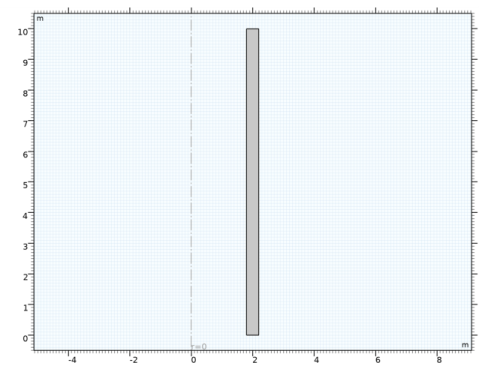
In the Model Builder window, under Component 2 (comp2)>Geometry 2 right-click Work Plane 1 (wp1) and choose Revolve.
2
In the Settings window for Revolve, locate the Revolution Angles section.
3
Click the Angles button.
4
In the End angle text field, type 15.
5
Click  Build All Objects.
Add Physics
1
In the Home toolbar, click  Add Physics to open the Add Physics window.
2
Go to the Add Physics window.
3
In the tree, select Structural Mechanics>Solid Mechanics (solid).
4
Click Add to Component 2 in the window toolbar.
5
In the Home toolbar, click  Add Physics to close the Add Physics window.
Solid Mechanics 2 (solid2)
Periodic Condition 1
1
Right-click Component 2 (comp2)>Solid Mechanics 2 (solid2) and choose Connections>Periodic Condition.
2
3
In the Settings window for Periodic Condition, locate the Periodicity Settings section.
4
From the Type of periodicity list, choose Cyclic symmetry.
Mesh 2
Mapped 1
1
In the Mesh toolbar, click  Boundary and choose Mapped.
2
Distribution 1
1
Right-click Mapped 1 and choose Distribution.
2
In the Settings window for Distribution, locate the Distribution section.
3
In the Number of elements text field, type 2.
4
Mapped 1
In the Model Builder window, right-click Mapped 1 and choose Build Selected.
Swept 1
In the Mesh toolbar, click  Swept.
Distribution 1
1
Right-click Swept 1 and choose Distribution.
2
In the Settings window for Distribution, locate the Distribution section.
3
In the Number of elements text field, type 20.
4
Click  Build All.
Materials
Material Link 3 (matlnk3)
In the Model Builder window, under Component 2 (comp2) right-click Materials and choose More Materials>Material Link.
Add Study
1
In the Home toolbar, click  Add Study to open the Add Study window.
2
Go to the Add Study window.
3
Find the Studies subsection. In the Select Study tree, select General Studies>Eigenfrequency.
4
Find the Physics interfaces in study subsection. In the table, clear the Solve check boxes for Solid Mechanics (solid) and Shell (shell).
5
Click Add Study in the window toolbar.
6
In the Home toolbar, click  Add Study to close the Add Study window.
Study 3, 3D solid sector
1
In the Model Builder window, click Study 3.
2
In the Settings window for Study, type Study 3, 3D solid sector in the Label text field.
Step 1: Eigenfrequency
1
In the Model Builder window, under Study 3, 3D solid sector click Step 1: Eigenfrequency.
2
In the Settings window for Eigenfrequency, locate the Study Settings section.
3
Select the Desired number of eigenfrequencies check box.
4
5
In the Model Builder window, collapse the Study 3, 3D solid sector node.
6
In the Home toolbar, click  Compute.
Results
Mode Shape (solid2)
1
In the Settings window for 3D Plot Group, locate the Data section.
2
From the Eigenfrequency (Hz) list, choose 243.5.
3
In the Mode Shape (solid2) toolbar, click  Plot.
Sector 3D 1
1
In the Results toolbar, click  More Datasets and choose Sector 3D.
2
In the Settings window for Sector 3D, locate the Symmetry section.
3
In the Number of sectors text field, type 360/15.
4
From the Sectors to include list, choose Manual.
5
In the Start sector text field, type 18.
6
In the Number of sectors to include text field, type 15.
Mode Shape (solid2)
1
In the Model Builder window, click Mode Shape (solid2).
2
In the Settings window for 3D Plot Group, locate the Data section.
3
From the Dataset list, choose Sector 3D 1.
4
Click the  Zoom Extents button in the Graphics toolbar.
5
In the Mode Shape (solid2) toolbar, click  Plot.
6
Click the  Show Grid button in the Graphics toolbar.
Also twisting modes can be displayed.
7
From the Eigenfrequency (Hz) list, choose 155.04.
8
In the Mode Shape (solid2) toolbar, click  Plot.
Solid Mechanics (solid)
The twisting modes can also be computed using the axisymmetric Solid Mechanics interface. To do that, use circumferential mode extension.
1
In the Model Builder window, under Component 1 (comp1) click Solid Mechanics (solid).
2
In the Settings window for Solid Mechanics, locate the Axial Symmetry Approximation section.
3
Select the Circumferential mode extension (time-harmonic) check box.
Study 1, 2D axisymmetric solid
Step 1: Eigenfrequency
1
In the Model Builder window, under Study 1, 2D axisymmetric solid click Step 1: Eigenfrequency.
2
In the Settings window for Eigenfrequency, locate the Physics and Variables Selection section.
3
In the table, clear the Solve for check boxes for Shell (shell) and Solid Mechanics 2 (solid2).
4
Locate the Study Settings section. Select the Desired number of eigenfrequencies check box.
5
6
In the Home toolbar, click  Compute.
Results
Mode Shape, 3D (solid)
In the Model Builder window, expand the Results>Mode Shape, 3D (solid) node.
Deformation
To display also twisting modes, add the rotational displacement component to the deformation.
1
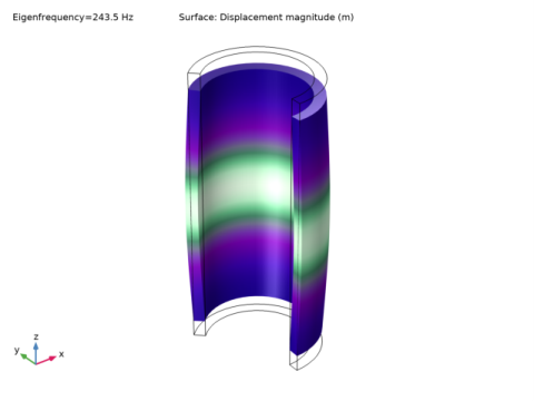
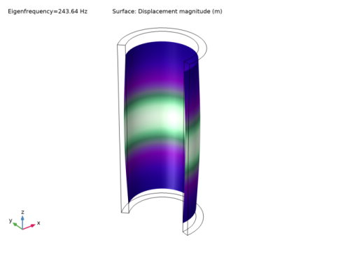
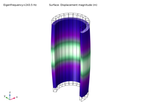
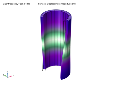
In the Model Builder window, expand the Results>Mode Shape, 3D (solid)>Surface 1 node, then click Deformation.
2
In the Settings window for Deformation, locate the Expression section.
3
In the PHI component text field, type v.
Mode Shape, 3D (solid)
Display the first twist mode.
1
In the Model Builder window, click Mode Shape, 3D (solid).
2
In the Settings window for 3D Plot Group, locate the Data section.
3
From the Eigenfrequency (Hz) list, choose 155.04.
4
In the Mode Shape, 3D (solid) toolbar, click  Plot.
5
From the Eigenfrequency (Hz) list, choose 243.5.
6
In the Mode Shape, 3D (solid) toolbar, click  Plot.
Study 2, 2D axisymmetric shell
Step 1: Eigenfrequency
1
In the Model Builder window, under Study 2, 2D axisymmetric shell click Step 1: Eigenfrequency.
2
In the Settings window for Eigenfrequency, locate the Physics and Variables Selection section.
3
In the table, clear the Solve for check box for Solid Mechanics 2 (solid2).