|
|
|
|
1
|
|
2
|
|
1
|
|
2
|
|
3
|
|
4
|
Find the Origin subsection. In the table, enter the following settings:
|
|
5
|
|
6
|
|
1
|
|
2
|
|
3
|
|
4
|
|
5
|
|
1
|
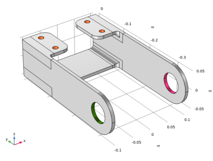
In the Model Builder window, expand the Component 1 (comp1)>Solid Mechanics (solid) node, then click Boundary Load 1.
|
|
2
|
|
3
|
|
4
|
|
1
|
|
2
|
|
3
|
|
4
|
Click
|
|
6
|
|
7
|
|
1
|
|
2
|
|
3
|
|
4
|
|
5
|
|
6
|
|
1
|
|
2
|
|
1
|
Go to the Table window.
|
|
2
|
|
1
|
|
2
|
|
3
|
|
4
|
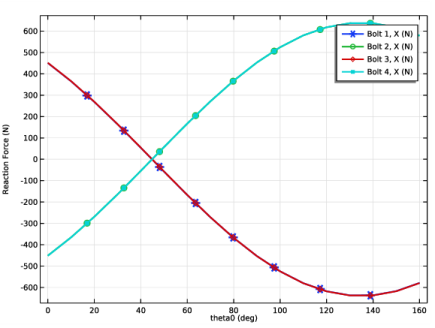
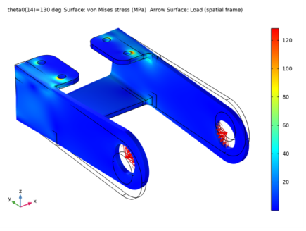
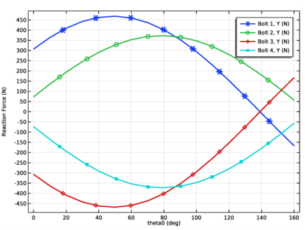
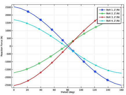
In the associated text field, type Reaction Force (N).
|
|
1
|
|
2
|
|
3
|
|
4
|
|
5
|
|
6
|
|
7
|
|
1
|
|
2
|
|
3
|
|
1
|
|
2
|
|
3
|
|
1
|
|
2
|
|
3
|
|
1
|
|
2
|
|
3
|