PDF

Damping Coefficients of a Squeeze Film Damper
Introduction
Squeeze film dampers are components that provide additional damping to rotating machines. To simplify the modeling of a rotor assembly, squeeze film dampers are often modeled in terms of their damping coefficients. This model computes damping coefficients for a short squeeze film damper and compares them to analytically computed values. The damping coefficients depend on the journal location in the damper.
Model Definition
The plain squeeze film damper has a radius of 0.1 m and length of 0.01 m. The journal undergoes a circular whirl at 100 rpm, and the clearance between the journal and the damper bushing is 0.001 m. The viscosity and density of the lubricant are taken as 0.02 Pa·s and 864 kg/m3, respectively. The relative eccentricity of the journal is varied from 0 to 0.95 in the steps of 0.05. The attitude angle is specified relative to the static load on the damper at . The damping coefficients are computed for all eccentricity values by solving a perturbed form of Reynolds equation.
The local directions of the damper are aligned with the global y and z directions, with the negative z direction defining . The attitude angle of the journal measured from the local y direction is therefore .The coordinates of the journal location in the damper, in local directions, are given by
where C is the clearance and ε is the relative eccentricity of the journal. Analytical values for the radial and tangential dimensionless damping coefficients (Ref. 1) are given by:
A dimensional scaling factor for the damping coefficients is μR(L/C)3. The damping coefficients are transformed from global to local coordinates as:
Results and Discussion
Figure 1 shows the various components of the computed damping coefficients and compares them to their analytical counterparts. The computed values match the analytical values.
Figure 1: Damping coefficients.
Reference
1. W.J. Chen and E.J. Gunter, Introduction to the Dynamics of Rotor-Bearing Systems, sections 6.10 and 6.11, pp. 263–271, Trafford Publishing, 2007.
Application Library path: Rotordynamics_Module/Verification_Examples/squeeze_film_damper_damping_coefficients
Modeling Instructions
From the File menu, choose New.
New
In the New window, click  Model Wizard.
Model Wizard
1
In the Model Wizard window, click  3D.
2
In the Select Physics tree, select Structural Mechanics>Rotordynamics>Hydrodynamic Bearing (hdb).
3
Click Add.
4
Click  Study.
5
In the Select Study tree, select General Studies>Stationary.
6
Create the parameters for the damper and lubricants properties.
Global Definitions
Parameters 1
1
In the Model Builder window, under Global Definitions click Parameters 1.
2
In the Settings window for Parameters, locate the Parameters section.
3
Geometry 1
Cylinder 1 (cyl1)
1
In the Geometry toolbar, click  Cylinder.
2
In the Settings window for Cylinder, locate the Size and Shape section.
3
In the Radius text field, type Rj.
4
In the Height text field, type H.
5
Locate the Axis section. From the Axis type list, choose x-axis.
6
Locate the Object Type section. From the Type list, choose Surface.
7
Click  Build Selected.
Define the variables for the analytical damping coefficients in local y and z directions.
Definitions
Variables 1
1
In the Model Builder window, under Component 1 (comp1) right-click Definitions and choose Variables.
2
In the Settings window for Variables, locate the Variables section.
3
Hydrodynamic Bearing (hdb)
1
In the Model Builder window, under Component 1 (comp1) click Hydrodynamic Bearing (hdb).
2
In the Settings window for Hydrodynamic Bearing, locate the Dynamic Coefficients section.
3
Select the Calculate dynamic coefficients check box.
Squeeze Film Damper 1
1
In the Physics toolbar, click  Boundaries and choose Squeeze Film Damper.
2
In the Settings window for Squeeze Film Damper, locate the Boundary Selection section.
3
From the Selection list, choose All boundaries.
4
Locate the Damper Properties section. In the C text field, type C.
5
Locate the Journal Properties section. From the Specify list, choose Eccentricity and direction.
6
In the e text field, type C*e.
7
In the φy text field, type 270[deg]+phi.
8
In the ω text field, type 2*pi[rad]*fr.
9
Locate the Film Boundary Condition section. From the Film type list, choose Gümbel.
10
Locate the Fluid Properties section. From the μ list, choose User defined. In the associated text field, type mu0.
11
From the ρ list, choose User defined. In the associated text field, type rho0.
Use a mapped mesh to resolve the pressure.
Mesh 1
Mapped 1
1
In the Mesh toolbar, click  Boundary and choose Mapped.
2
In the Settings window for Mapped, locate the Boundary Selection section.
3
From the Selection list, choose All boundaries.
Distribution 1
1
Right-click Mapped 1 and choose Distribution.
2
3
In the Settings window for Distribution, locate the Distribution section.
4
In the Number of elements text field, type 50.
Distribution 2
1
In the Model Builder window, right-click Mapped 1 and choose Distribution.
2
3
In the Settings window for Distribution, click  Build All.
Study 1
Step 1: Stationary
1
In the Model Builder window, under Study 1 click Step 1: Stationary.
2
In the Settings window for Stationary, click to expand the Study Extensions section.
3
Select the Auxiliary sweep check box.
4
5
6
7
In the Home toolbar, click  Compute.
Results
Fluid Pressure (hdb)
1
In the Fluid Pressure (hdb) toolbar, click  Plot.
Pressure in the damper is the default plot. Follow the below instructions to compare the computed and the analytical values of the dimensionless damping for the damper as shown in Figure 1.
Damping coefficients (Dimensionless)
1
In the Home toolbar, click  Add Plot Group and choose 1D Plot Group.
2
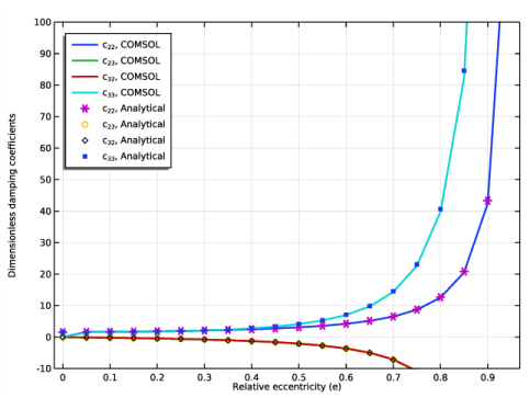
In the Settings window for 1D Plot Group, type Damping coefficients (Dimensionless) in the Label text field.
Global 1
1
Right-click Damping coefficients (Dimensionless) and choose Global.
2
In the Settings window for Global, click Replace Expression in the upper-right corner of the y-Axis Data section. From the menu, choose Component 1 (comp1)>Hydrodynamic Bearing>Dynamic coefficients>hdb.sfd1.c22 - Bearing damping coefficient, local yy component - N·s/m.
3
Locate the y-Axis Data section. In the table, enter the following settings:
4
Click to expand the Coloring and Style section. In the Width text field, type 2.
Global 2
1
In the Model Builder window, right-click Damping coefficients (Dimensionless) and choose Global.
2
In the Settings window for Global, locate the y-Axis Data section.
3
4
Locate the Coloring and Style section. Find the Line style subsection. From the Line list, choose None.
5
Find the Line markers subsection. From the Marker list, choose Cycle.
6
From the Positioning list, choose In data points.
Damping coefficients (Dimensionless)
1
In the Model Builder window, click Damping coefficients (Dimensionless).
2
In the Settings window for 1D Plot Group, locate the Plot Settings section.
3
Select the x-axis label check box.
4
In the associated text field, type Relative eccentricity (e).
5
Select the y-axis label check box.
6
In the associated text field, type Dimensionless damping coefficients.
7
Click to expand the Title section. From the Title type list, choose None.
8
Locate the Legend section. From the Position list, choose Upper left.
9
Locate the Axis section. Select the Manual axis limits check box.
10
In the y minimum text field, type -10.
11
In the y maximum text field, type 100.
12
In the Damping coefficients (Dimensionless) toolbar, click  Plot.