PDF

Linear Wave Retarder
Introduction
The intensity and polarization of light can be accurately controlled by transmitting it through various types of optical components. While it is possible to model complex changes in ray polarization by applying a customized Mueller matrix to rays at a single boundary, the same result can often be achieved by placing several simpler optical components in series. This tutorial model shows how the polarization of radiation can be manipulated using a combination of linear polarizers and linear wave retarders.
An ideal linear polarizer is a device that only transmits radiation for which the electric field lies within a plane. The intersection of this plane with the polarizer forms a line known as the transmission axis.
An ideal linear wave retarder is an optical device that applies a phase shift to radiation polarized in one direction with respect to radiation polarized in an orthogonal direction. The plane of linear polarization that corresponds to the direction of minimal phase retardation, when intersected with the surface of the wave retarder, yields a line known as the fast axis. The phase shift between radiation polarized parallel to and perpendicular to the fast axis is known as the retardance of the device.
By combining linear wave retarders and linear polarizers in series and varying their orientations and retardance values, it is possible to control the intensity of emitted radiation and to produce light in any state of linear, circular, or elliptical polarization.
Stokes Vectors and Optical Components
The intensity and polarization of a ray of light can be described by a 4-vector known as the Stokes vector, whose components are called the Stokes parameters. The first Stokes parameter is the ray intensity, the second and third parameters indicate linear polarization in various directions, and the fourth and final parameter corresponds to the degree of circular polarization. A more in-depth explanation of the physical meaning of the Stokes parameters can be found in the Ray Optics Module User’s Guide.
For example, a ray of natural (unpolarized) light with intensity I0 has Stokes vector
(1)
The Stokes vector of linearly polarized light varies depending on the direction of polarization. If the light is polarized in the direction of the x-axis, the Stokes vector is
(2)
For right-hand circularly polarized light the Stokes vector is
(3)
Varying states of elliptical polarization can be defined by specifying nonzero values of all of the Stokes parameters. In general, the light ray is fully polarized if the L2 norm of the second, third, and fourth parameters equals the first parameter or ray intensity.
In the Geometrical Optics interface, optical components such as linear polarizers and wave retarders are implemented as boundary conditions that don’t affect the ray path but do change the Stokes parameters, which are stored as separate degrees of freedom for each ray. The effect of any optical component or system of optical components can be represented by a 4 × 4 Mueller matrix M. The Mueller matrix is multiplied by the Stokes vector of the incoming ray to produce a new Stokes vector for the transmitted ray,
where si is the Stokes vector of the incident ray. A rotation matrix R is included to account for the orientation of the optical component with respect to the coordinate system in which the ray’s Stokes parameters are defined.
Linear Polarizer
A linear polarizer transforms any incident light ray into a linearly polarized ray. Its Mueller matrix is
(4)
The orientation of the linear polarizer is specified by defining a direction called the transmission axis T. Light that is polarized in the direction parallel to the fast axis is completely transmitted, whereas light that is polarized in the orthogonal direction is completely blocked. The matrix R is then the rotation matrix from the coordinate system in which the Stokes parameters are defined to a coordinate system in which the transmission axis is parallel to the x-axis.
To see how the Mueller matrix in Equation 4 produces linearly polarized light, consider its effect on natural light (Equation 1):
(5)
The transmitted light has half the intensity of the incident light and is linearly polarized. Linear polarization in any other direction can be achieved by including the rotation matrix R in Equation 5. This is equivalent to changing the orientation of the linear polarizer; that is, rotating the transmission axis.
Linear Wave Retarder
A linear wave retarder applies a phase delay to linearly polarized light in one direction, relative to linearly polarized light in the orthogonal direction. Its Mueller matrix is
(6)
The orientation of the linear wave retarder is specified by defining a direction called the fast axis F. Light that is polarized in the direction parallel to the fast axis is subjected to the minimum phase delay, whereas light that is polarized in the orthogonal direction is subjected to the maximum phase delay. The matrix R is then the rotation matrix from the coordinate system in which the Stokes parameters are defined to a coordinate system in which the fast axis is parallel to the x-axis. The relative phase delay δ is called the retardance.
A linear wave retarder has no discernible effect on natural light; this can be seen by combining Equation 1 and Equation 6 for any value of δ:
A quarter-wave retarder (δ = π/2) can convert linearly polarized light into circularly polarized light if the incident light is linearly polarized at a 45° angle with respect to the fast axis:
A half-wave retarder (δ = π) can convert right-hand circularly polarized light into left-hand circularly polarized light and vice-versa:
Combining Optical Components
A combination of several optical components in series can be modeled by defining a Mueller matrix for each layer. Alternatively, it is possible to specify a single Mueller matrix, which is the product of the Mueller matrices for all of the optical components; if there are N optical components such that M1 is the Mueller matrix of the first component encountered and MN is the component of the last component encountered, the equivalent Mueller matrix Meq is
In this example, the individual polarizers and wave retarders are instead handled as separate entities, so that the effect of each optical component on the intensity and polarization of the transmitted light can be observed in greater detail.
Model Definition
The model geometry consists of three parallel surfaces, all of which are parallel to the xy-plane. The first and last boundaries are assigned the Linear Polarizer boundary condition, one with a transmission axis parallel to the x-axis and the other with a transmission axis parallel to the y-axis. The middle boundary is assigned the Linear Wave Retarder boundary condition with a fast axis parallel to the line y = x; it makes a 45° angle with the transmission axes of both polarizers.
Without the linear wave retarder, no radiation would propagate through the assembly of polarizers. However, by varying the retardance, the linearly polarized ray transmitted by the first polarizer can be converted to a ray of circular polarization, elliptical polarization, or linear polarization in a different direction before reaching the second polarizer, thus allowing some of the light to be transmitted.
Results and Discussion
When the linear wave retarder is given zero retardance, the series of optical devices consists of two linear polarizers with orthogonal transmission axes. As shown in Figure 1, the first linear polarizer reduces the ray intensity by half, as indicated by the color expression. The transmitted ray is also linearly polarized, as indicated by the deformation of the ray trajectory. The second linear polarizer reduces the ray intensity to zero.
When the linearly polarized ray is transmitted through a quarter-wave retarder, the intensity of the ray transmitted by the second linear polarizer is nonzero, as shown in Figure 2. The quarter-wave retarder converts the incident linearly polarized ray to a circularly polarized ray without changing its intensity. Then half of the intensity of the circularly polarized ray is transmitted through the second polarizer, which returns it to a state of linear polarization.
When the quarter-wave retarder is replaced with a half-wave retarder, the incident linearly polarized ray is instead converted to linearly polarized radiation with an orthogonal polarization. As a result, the second linear polarizer does not cause any noticeable decrease in the ray intensity, as shown in Figure 3.
Figure 1: A ray passing through two linear polarizers. The final intensity is zero.
Figure 2: Passage of a linearly polarized ray through a quarter-wave retarder between two linear polarizers. The final intensity is 1/4 of the initial intensity.
Figure 3: Passage of a linearly polarized ray through a half-wave retarder between two linear polarizers. The final intensity is 1/2 of the initial intensity.
Application Library path: Ray_Optics_Module/Tutorials/linear_wave_retarder
Modeling Instructions
From the File menu, choose New.
New
In the New window, click  Model Wizard.
Model Wizard
1
In the Model Wizard window, click  3D.
2
In the Select Physics tree, select Optics>Ray Optics>Geometrical Optics (gop).
3
Click Add.
4
Click  Study.
5
In the Select Study tree, select Preset Studies for Selected Physics Interfaces>Ray Tracing.
6
Global Definitions
Parameters 1
1
In the Model Builder window, under Global Definitions click Parameters 1.
2
In the Settings window for Parameters, locate the Parameters section.
3
Geometry 1
The geometry contains no domains and consists of three parallel surfaces, at which the boundary conditions will be applied.
Work Plane 1 (wp1)
1
In the Geometry toolbar, click  Work Plane.
2
In the Settings window for Work Plane, locate the Plane Definition section.
3
In the z-coordinate text field, type 1.
Work Plane 1 (wp1)>Plane Geometry
In the Model Builder window, click Plane Geometry.
Work Plane 1 (wp1)>Square 1 (sq1)
1
In the Work Plane toolbar, click  Square.
2
In the Settings window for Square, locate the Position section.
3
From the Base list, choose Center.
4
In the Model Builder window, click Geometry 1.
Array 1 (arr1)
1
In the Geometry toolbar, click  Transforms and choose Array.
2
3
In the Settings window for Array, locate the Size section.
4
From the Array type list, choose Linear.
5
In the Size text field, type 3.
6
Locate the Displacement section. In the z text field, type 1.
7
Click  Build All Objects.
8
Click the  Zoom Extents button in the Graphics toolbar.
Geometrical Optics (gop)
Since no reflection at material discontinuities occurs in this model, set the number of secondary rays to zero.
1
In the Model Builder window, under Component 1 (comp1) click Geometrical Optics (gop).
2
In the Settings window for Geometrical Optics, locate the Ray Release and Propagation section.
3
In the Maximum number of secondary rays text field, type 0.
4
Locate the Intensity Computation section. From the Intensity computation list, choose Compute intensity.
Release from Grid 1
1
In the Physics toolbar, click  Global and choose Release from Grid.
2
In the Settings window for Release from Grid, locate the Ray Direction Vector section.
3
Specify the L0 vector as
Create a pair of linear polarizers with orthogonal transmission axes.
Linear Polarizer 1
1
In the Physics toolbar, click  Boundaries and choose Linear Polarizer.
2
Linear Polarizer 2
1
In the Physics toolbar, click  Boundaries and choose Linear Polarizer.
2
3
In the Settings window for Linear Polarizer, locate the Device Properties section.
4
Specify the T vector as
Next, add a quarter-wave retarder to enable a fraction of the energy of the ray to propagate through the second polarizer.
Linear Wave Retarder 1
1
In the Physics toolbar, click  Boundaries and choose Linear Wave Retarder.
2
3
In the Settings window for Linear Wave Retarder, locate the Device Properties section.
4
Specify the F vector as
5
In the δ text field, type delta.
Study 1
Parametric Sweep
1
In the Study toolbar, click  Parametric Sweep.
The study uses three different retardance values. For δ = 0 the Linear wave retarder boundary condition has no effect. For δ /2 a quarter-wave retarder is used. For δ a half-wave retarder is used.
2
In the Settings window for Parametric Sweep, locate the Study Settings section.
3
4
Step 1: Ray Tracing
1
In the Model Builder window, click Step 1: Ray Tracing.
2
In the Settings window for Ray Tracing, locate the Study Settings section.
3
From the Time-step specification list, choose Specify maximum path length.
4
Click  Range.
5
In the Range dialog box, type 0.1 in the Step text field.
6
In the Stop text field, type 4.
7
Click Replace.
8
In the Study toolbar, click  Compute.
Results
No Wave Retarder
1
In the Settings window for 3D Plot Group, locate the Data section.
2
From the Parameter value (delta (rad)) list, choose 0.
3
In the Label text field, type No Wave Retarder.
4
Locate the Plot Settings section. Clear the Plot dataset edges check box.
Modify the default plot to indicate the intensity and polarization of the ray.
Ray Trajectories 1
1
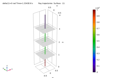
In the Model Builder window, expand the Ray Trajectories (gop) node, then click Results>No Wave Retarder>Ray Trajectories 1.
2
In the Settings window for Ray Trajectories, locate the Coloring and Style section.
3
Find the Line style subsection. From the Type list, choose Tube.
Color Expression 1
1
In the Model Builder window, expand the Ray Trajectories 1 node, then click Color Expression 1.
2
In the Settings window for Color Expression, locate the Coloring and Style section.
3
From the Color table list, choose Spectrum.
Ray Trajectories 1
1
In the Model Builder window, click Ray Trajectories 1.
2
In the Settings window for Ray Trajectories, locate the Coloring and Style section.
3
Find the Point style subsection. From the Type list, choose Ellipse.
4
In the Maximum number of ellipses text field, type 25.
5
Select the Ellipse scale factor check box.
6
Surface 1
1
In the Model Builder window, right-click No Wave Retarder and choose Surface.
2
In the Settings window for Surface, locate the Data section.
3
From the Dataset list, choose Study 1/Solution 1 (sol1).
4
Locate the Coloring and Style section. From the Coloring list, choose Uniform.
5
From the Color list, choose Gray.
6
In the No Wave Retarder toolbar, click  Plot.
7
Click the  Go to Default View button in the Graphics toolbar.
Compare the resulting image to Figure 1.
Quarter-Wave Retarder
1
Right-click No Wave Retarder and choose Duplicate.
2
In the Settings window for 3D Plot Group, type Quarter-Wave Retarder in the Label text field.
3
Locate the Data section. From the Parameter value (delta (rad)) list, choose 1.5708.
4
In the Quarter-Wave Retarder toolbar, click  Plot.
Compare the resulting image to Figure 2. The quarter-wave retarder causes a phase shift between the electric field components parallel to and perpendicular to the fast axis. As a result, the linearly polarized ray becomes circularly polarized. Upon reaching the second linear polarizer, the ray intensity is reduced by half.
Half-Wave Retarder
1
Right-click Quarter-Wave Retarder and choose Duplicate.
2
In the Settings window for 3D Plot Group, type Half-Wave Retarder in the Label text field.
3
Locate the Data section. From the Parameter value (delta (rad)) list, choose 3.1416.
4
In the Half-Wave Retarder toolbar, click  Plot.
Compare the resulting image to Figure 3. While propagating through the half-wave retarder, the ray remains linearly polarized, but the direction of polarization is rotated. The ray then propagates through the second linear polarizer without any loss of intensity.