PDF

Total Internal Reflection Thin-Film Achromatic Phase Shifter (TIRTF APS)
Introduction
The capability to alter the polarization of light is crucial to a wide variety of optical devices. For example, the polarization of light has a significant effect on the performance of optical isolators, attenuators, and beam splitters. By assigning a specific polarization to light, most notably linear or circular polarization, it is possible to substantially reduce glare in optical systems. Linearly and circularly polarized light are widely used in metrology applications, such as stress analysis and biological diagnosis, and in imaging applications such as the design of camera and video equipment.
One of the most fundamental methods of manipulating polarization is wave retardation, in which one component of the electric field is subjected to a phase delay, or retarded, relative to the orthogonal electric field component in a propagating beam of light.
Of particular interest is a quarter-wave retarder, which imposes a 90° phase delay between the two orthogonal components of the electric field. Quarter-wave retarders can be used to convert linearly polarized light into circularly or elliptically polarized light. By combining quarter-wave retarders and linear polarizers it is possible, for example, to design an optical isolator that transmits incoming radiation but blocks scattered or reflected radiation from returning to the source.
In this tutorial, the phenomenon of total internal reflection is used to design and model an achromatic phase shifter, or a wave retarder that exhibits nearly uniform phase delay over a wide spectral range. The importance of thin dielectric films in achieving such a uniform wave retardation is discussed.
Model Background
Two types of quarter-wave retarder are discussed in this section: birefringent wave plates and prisms exploiting total internal reflection. The latter is the subject of this tutorial.
Birefringent Wave Plates
A conventional wave plate is a birefringent crystal that causes a phase delay between two orthogonal components of the electric field of a propagating ray by allowing these components to propagate at slightly different speeds. Typically, a wave plate is made of a uniaxial material that introduces a relative phase delay δ (SI unit: rad) between the two orthogonal field components given by
(1)
where λ0 (SI unit: m) is the free-space wavelength of the radiation, L is the thickness of the wave plate, and Δn is the difference in refractive index between the ordinary axis and extraordinary axis of the crystal. Because linearly polarized light in the direction of the ordinary or extraordinary axes of a birefringent crystal would propagate at different group velocities, linearly polarized light at a 45° angle to these two axes will show a gradual retardation of one component with respect to the orthogonal component, eventually converting the linearly polarized light to circularly polarized light. This phenomenon is illustrated in Figure 1 below.
Figure 1: Evolution of the instantaneous electric field amplitude in a wave plate. A birefringent medium exists between the two surfaces, which ordinary and extraordinary axes parallel to the x- and y-axes. As the linearly polarized ray propagates in the +z-direction, it gradually becomes circularly polarized.
A fundamental shortcoming of birefringent wave plates is that they are inherently wavelength-dependent. As shown in Equation 1, the phase shift is inversely proportional to the vacuum wavelength. Typically retarders that introduce phase delays of 90° or 180° are the most useful, and by using a wave plate it would only be possible to get the desired phase delay for specific wavelengths.
An alternative, which is explored in this example, is to use the phenomenon of total internal reflection to design a quarter-wave retarder that is achromatic; that is, a quarter-wave retarder that creates a nearly constant phase delay across a range of vacuum wavelengths.
Reflection and Refraction of Light at Material Discontinuities
To quantify the phase delays introduced by total internal reflections within a glass prism, a preliminary understanding of the fundamentals of reflection and refraction of light is required. The following is explained in more detail in Ref. 1 and in the Ray Optics Module User’s Guide.
When a ray of light reaches the boundary between two dielectric media, a refracted ray is released in a direction determined by Snell’s law,
(2)
where
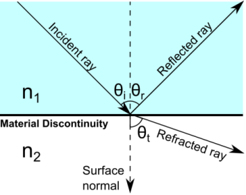
n1 (dimensionless) is the refractive index of the medium containing the incident ray,
n2 (dimensionless) is the refractive index of the medium containing the refracted ray,
θi (SI unit: rad) is the angle of incidence, and
θt (SI unit: rad) is the angle of refraction.
Alternatively, Snell’s law may be written as
(3)
This form of Snell’s law will later be useful for deriving the phase delay induced by total internal reflection.
In addition to the refracted ray described above, a reflected ray is released with an angle of reflection equal to the angle of incidence. The incident ray, reflected ray, refracted ray, and surface normal all lie within the same plane, called the plane of incidence. These angles are illustrated below.
Figure 2: Incident, reflected, and refracted rays at an interface between two materials of different refractive indices.
The electric field amplitudes of the reflected and refracted rays are related to the amplitude of the incident ray by the Fresnel Equations:
(4)
(5)
(6)
(7)
where
The variables r and t are called the reflection coefficient and transmission coefficient, respectively. For example, Equation 4 yields the reflection coefficient of p-polarized radiation, or radiation polarized so that the electric field vector lies in the plane of incidence.
The ratio of the intensities of the transmitted and reflected rays to the intensity of the incident ray are called the transmittance T and reflectance R, respectively, given by
(8)
(9)
By substituting the definitions of the Fresnel coefficients for either s- or p-polarized radiation into Equation 8 and Equation 9, one obtains R + T = 1.
If the ray is propagating from a medium of higher refractive index to a medium of lower refractive index, that is, n2 < n1, then there exists a maximum value of the angle of incidence, beyond which no real value of the angle of refraction exists. This is the critical angle θc, given by
(10)
which is also the angle at which the radicand in Equation 3 equals zero. When the angle of incidence is greater than the critical angle, that is, θi > θc, the ray is completely reflected and no refracted ray can propagate in the adjacent domain. This phenomenon is called total internal reflection. Because θi > θc, it follows from Equation 3 that cos θt has a value on the positive imaginary axis in the complex plane. Therefore, according to Equation 9 the refracted wave is evanescent, so 100 % of the energy of the incident ray is reflected.
Substitution of Equation 3 into Equation 6 and Equation 7, taking into account the previous observation that cos θt is imaginary, yields
Let n = n2 / n1; then further simplification yields
(11)
(12)
Let δp and δs be the arguments of the complex-valued quantities rp and rs, respectively. Then it follows from Equation 11 and Equation 12 that
(13)
(14)
The phase delay introduced by the total internal reflection is the difference between the two arguments,
Using the difference identity
and substituting Equation 13 and Equation 14 yields an expression for the phase delay,
(15)
Equation 15 is an expression for the phase delay that doesn’t depend on the vacuum wavelength, and therefore can be considered an achromatic phase shifter. However, several technical complications arise when using total internal reflection to induce a 90° phase shift:
Most common optical materials don’t have sufficiently large refractive indices to induce a 90° phase shift with a single reflection. For example, if the region surrounding the prism is an air or vacuum domain (n2 = 1), then the smallest real value of the refractive index is approximately n1 = 2.414 for an angle of incidence of about θi = 32.9°. If the angle of incidence is 45° or greater, then no real finite value of n2 will yields a 90° phase delay. Therefore, most practical designs would require light to be reflected at least twice, with a smaller phase delay (say, 45°) during each reflection. The Fresnel rhomb, for example, subjects light to two consecutive total internal reflections to cause a total phase delay of 90°.
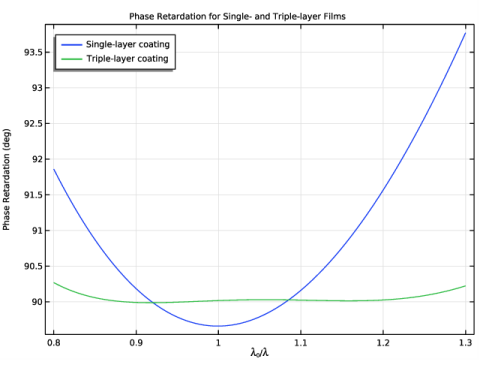
Equation 15 can still depend on the vacuum wavelength indirectly because of its dependence on the refractive index ratio n. Most real media are dispersive to some extent; that is, the refractive index is a function of the vacuum wavelength.
Equation 15 is heavily dependent on the angle of incidence θi, and will therefore yield dramatically different phase delays if the incident beam is not collimated; that is, if not all of the incoming rays reach the surface at exactly the specified angle of incidence.
In this tutorial, the dispersive medium and the dependence on the angle of incidence are not considered. However, it will be shown that a greater phase delay can be achieved during a single total internal reflection by coating the surface of the prism with thin dielectric layers.
Thin Dielectric Films
The interface between two media can be coated with one or more thin dielectric films to change the coefficients of reflection and transmission. By “thin” it is usually meant that the film is comparable in thickness to the wavelength of the radiation, but for the following analysis the only requirement is that the thickness of the film is much smaller than the coherence length of the radiation. When the incident ray enters a thin dielectric film, it is reflected back and forth at the two adjacent surfaces, producing many refracted rays in each region.
Figure 3: Visualization of the reflected and refracted rays that are created as an incident ray crosses a thin dielectric film.
All of the rays that propagate into either region can interfere constructively or destructively with each other due to the coherent nature of the radiation. The net effect of superposing all of these escaping rays can be considered by replacing the thin film with a fictitious surface with complex Fresnel coefficients:
(16)
(17)
(18)
Because the Fresnel coefficients are complex, they induce phase delays on the reflected and refracted rays. Furthermore, simply changing the thickness of the film affects the arguments of the reflection and transmission coefficients. Therefore, thin films offer much more precise control over the phase delays at air-dielectric interfaces compared to uncoated prisms. However, as shown in Equation 18, the thin films introduce a degree of wavelength-dependence that is not seen during total internal reflection at uncoated boundaries. This can be compensated for by using multilayer films, which offer much more precise control of the phase delay over a range of wavelengths.
If multiple dielectric layers are adjacent to each other, the equivalent Fresnel coefficients for the multilayer film can be computed recursively, repeatedly using Equation 16 and Equation 17 while replacing r23 with the value of req from the previous iteration.
Model Definition
In this tutorial, a linearly polarized ray reaches the surface of a prism at an angle of incidence of 45°. The plane of polarization is at a 45° angle to the plane of incidence, so that the incoming ray is equal parts s- and p-polarized. Therefore, a 90° phase shift should produce circularly polarized light.
As explained in the previous section, no transparent dielectric material can induce a 90° phase delay for light at a 45° angle of incidence, so thin dielectric films must be used to achieve the desired phase delay with only one reflection. Following Ref. 2, the refractive index of the glass prism is np = 1.509 and the following combinations of thin films are used:
1
Single layer with n1 = 2.0535 and t1 = 0.089λ0.
2
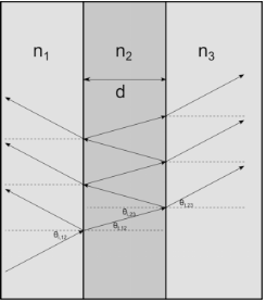
Triple layer with n1 = 2.346, n2 = 1.664, n3 = 1.496, t1 = 0.0447λ0, t2 = 0.111λ0, and t3 = 0.3856λ0.
Results and Discussion
For the two combinations of thin dielectric films described in the previous section, the phase retardation as a function of free space wavelength is plotted in Figure 4. As is often the case with phase shifters using total internal reflection, a multilayer film offers more precise control over the retardance and reduces its wavelength dependence more than a single-layer film.
Figure 4: Phase retardation between the s- and p-polarized components of the electric field amplitude are plotted as a function of free space wavelength.
References
1. M. Born and E. Wolf, Principles of Optics, 7th ed., Cambridge, 1999.
2. Spiller, Eberhard. “Totally reflecting thin-film phase retarders.” Applied Optics 23, no. 20 (1984): 3544-3549.
3. King, R. J. “Quarter-wave retardation systems based on the Fresnel rhomb principle.” Journal of Scientific Instruments 43, no. 9 (1966): 617.
Application Library path: Ray_Optics_Module/Prisms_and_Coatings/achromatic_phase_shifter
Modeling Instructions
From the File menu, choose New.
New
In the New window, click  Model Wizard.
Model Wizard
1
In the Model Wizard window, click  3D.
2
In the Select Physics tree, select Optics>Ray Optics>Geometrical Optics (gop).
3
Click Add.
4
Click  Study.
5
In the Select Study tree, select Preset Studies for Selected Physics Interfaces>Ray Tracing.
6
Global Definitions
Parameters 1
Load a file containing parameters for the refractive index and thickness of each thin film.
1
In the Model Builder window, under Global Definitions click Parameters 1.
2
In the Settings window for Parameters, locate the Parameters section.
3
Click  Load from File.
4
Geometry 1
The geometry is a simple glass prism in which light is incident on the surface at a 45-degree angle.
Work Plane 1 (wp1)
In the Geometry toolbar, click  Work Plane.
Work Plane 1 (wp1)>Plane Geometry
In the Model Builder window, click Plane Geometry.
Work Plane 1 (wp1)>Polygon 1 (pol1)
1
In the Work Plane toolbar, click  Polygon.
2
In the Settings window for Polygon, locate the Coordinates section.
3
4
Click  Build Selected.
Work Plane 1 (wp1)
In the Model Builder window, click Work Plane 1 (wp1).
Extrude 1 (ext1)
1
In the Geometry toolbar, click  Extrude.
2
In the Settings window for Extrude, click  Build Selected.
3
Click the  Zoom Extents button in the Graphics toolbar.
Materials
Material 1 (mat1)
1
In the Materials toolbar, click  Blank Material.
2
In the Settings window for Material, locate the Material Contents section.
3
Geometrical Optics (gop)
Adjust the physics interface settings to allow different wavelengths to be released. This provides a more rigorous test of the achromaticity of the polarizer.
1
In the Model Builder window, under Component 1 (comp1) click Geometrical Optics (gop).
2
In the Settings window for Geometrical Optics, locate the Ray Release and Propagation section.
3
From the Wavelength distribution of released rays list, choose Polychromatic, specify vacuum wavelength.
4
In the Maximum number of secondary rays text field, type 0. Secondary rays are not needed because all of the primary rays undergo total internal reflection at the material discontinuity.
5
Locate the Intensity Computation section. From the Intensity computation list, choose Compute intensity. When the ray intensity is computed, information about the ray polarization is also available because the intensity calculation method allocates degrees of freedom for all four Stokes parameters.
Release from Grid 1
1
In the Physics toolbar, click  Global and choose Release from Grid.
2
In the Settings window for Release from Grid, locate the Initial Coordinates section.
3
In the qx,0 text field, type 0.2.
4
In the qy,0 text field, type 0.5.
5
In the qz,0 text field, type 0.5.
6
Locate the Ray Direction Vector section. Specify the L0 vector as
Specify the wavelength range of the released rays. One ray per wavelength value will be released at the specified point.
7
Locate the Vacuum Wavelength section. From the Distribution function list, choose List of values.
8
Click  Range.
9
In the Range dialog box, choose Number of values from the Entry method list.
10
In the Start text field, type lam0/0.8.
11
In the Stop text field, type lam0/1.3.
12
In the Number of values text field, type 100.
13
Click Replace.
Change the polarization of the incident ray so that it is linearly polarized at a 45-degree angle to the plane of incidence.
14
In the Settings window for Release from Grid, locate the Initial Polarization section.
15
From the Initial polarization type list, choose Fully polarized.
16
From the Initial polarization list, choose User defined.
17
In the a2,0 text field, type 1.
Because the default value of the Initial phase difference is zero, the release feature produces rays that are linearly polarized at a 45-degree angle to the direction specified in the Initial polarization reference direction field.
Create two instances of the Material Discontinuity boundary condition on the internally reflecting surface. These two features will be given different combinations of thin dielectric films and used in two separate studies.
Single-layer Coating
1
In the Physics toolbar, click  Boundaries and choose Material Discontinuity.
2
3
In the Settings window for Material Discontinuity, type Single-layer Coating in the Label text field.
4
Locate the Coatings section. From the Thin dielectric films on boundary list, choose Add layers to surface.
Thin Dielectric Film 1
1
In the Physics toolbar, click  Attributes and choose Thin Dielectric Film.
2
In the Settings window for Thin Dielectric Film, locate the Film Properties section.
3
In the n text field, type nf1.
4
In the t text field, type tf1.
Triple-layer Coating
1
In the Physics toolbar, click  Boundaries and choose Material Discontinuity.
2
3
In the Settings window for Material Discontinuity, type Triple-layer Coating in the Label text field.
4
Locate the Coatings section. From the Thin dielectric films on boundary list, choose Add layers to surface.
Thin Dielectric Film 1
1
In the Physics toolbar, click  Attributes and choose Thin Dielectric Film.
2
In the Settings window for Thin Dielectric Film, locate the Film Properties section.
3
In the n text field, type nf2.
4
In the t text field, type tf2.
Triple-layer Coating
In the Model Builder window, click Triple-layer Coating.
Thin Dielectric Film 2
1
In the Physics toolbar, click  Attributes and choose Thin Dielectric Film.
2
In the Settings window for Thin Dielectric Film, locate the Film Properties section.
3
In the n text field, type nf3.
4
In the t text field, type tf3.
Triple-layer Coating
In the Model Builder window, click Triple-layer Coating.
Thin Dielectric Film 3
1
In the Physics toolbar, click  Attributes and choose Thin Dielectric Film.
2
In the Settings window for Thin Dielectric Film, locate the Film Properties section.
3
In the n text field, type nf4.
4
In the t text field, type tf4.
Study 1
Step 1: Ray Tracing
1
In the Model Builder window, under Study 1 click Step 1: Ray Tracing.
2
In the Settings window for Ray Tracing, locate the Study Settings section.
3
From the Time-step specification list, choose Specify maximum path length.
4
In the Lengths text field, type 0 0.6.
In the first study, the single-layer coating is used, so the triple-layer coating must be disabled.
5
Locate the Physics and Variables Selection section. Select the Modify model configuration for study step check box.
6
In the Physics and variables selection tree, select Component 1 (comp1)>Geometrical Optics (gop)>Triple-layer Coating.
7
Click  Disable.
8
In the Home toolbar, click  Compute.
Results
Polarization Ellipses, Single-layer Coating
In the Settings window for 3D Plot Group, type Polarization Ellipses, Single-layer Coating in the Label text field.
Ray Trajectories 1
1
In the Model Builder window, expand the Polarization Ellipses, Single-layer Coating node, then click Ray Trajectories 1.
2
In the Settings window for Ray Trajectories, locate the Coloring and Style section.
3
Find the Point style subsection. From the Type list, choose Ellipse.
Color Expression 1
1
In the Model Builder window, expand the Ray Trajectories 1 node, then click Color Expression 1.
2
In the Settings window for Color Expression, locate the Expression section.
3
In the Expression text field, type gop.s3/gop.s0. This expression gives the degree of circular polarization, which has a magnitude of zero for linearly polarized or unpolarized radiation and unit magnitude for circularly polarized radiation.
4
In the Polarization Ellipses, Single-layer Coating toolbar, click  Plot.
5
Click the  Go to ZX View button in the Graphics toolbar. The polarization ellipses appear as line segments for the incident linearly polarized rays and circles for the reflected rays. The polarization ellipses and color expression confirm that the reflected rays are all nearly circularly polarized.
Phase Retardation vs. Wavelength
1
In the Home toolbar, click  Add Plot Group and choose 1D Plot Group.
2
In the Settings window for 1D Plot Group, type Phase Retardation vs. Wavelength in the Label text field.
3
Locate the Data section. From the Dataset list, choose Ray 1.
4
From the Time selection list, choose Last.
5
Click to expand the Title section. From the Title type list, choose Manual.
6
In the Title text area, type Phase Retardation for Single- and Triple-layer Films.
7
Locate the Plot Settings section. Select the x-axis label check box.
8
In the associated text field, type \lambda<sub>0</sub>/\lambda.
9
Select the y-axis label check box.
10
In the associated text field, type Phase Retardation (deg).
11
Locate the Legend section. From the Position list, choose Upper left.
Ray 1
1
In the Phase Retardation vs. Wavelength toolbar, click  More Plots and choose Ray.
It is convenient to use the Ray plot because it can be used to compare any two variables that are defined for all rays.
2
In the Settings window for Ray, locate the y-Axis Data section.
3
In the Expression text field, type mod(gop.delta-at(0,gop.delta),180[deg]).
4
From the Unit list, choose °.
5
Locate the x-Axis Data section. From the Parameter list, choose Expression.
6
In the Expression text field, type lam0/gop.lambda0.
7
Click to expand the Legends section. Select the Show legends check box.
8
From the Legends list, choose Manual.
9
10
In the Phase Retardation vs. Wavelength toolbar, click  Plot.
The plot shows the phase shift as a function of the free-space wavelength of the radiation. When a single-layer film is used, the phase shift varies by about 4 degrees over the simulated frequency range. Now repeat the analysis using a multilayer film.
Add Study
1
In the Home toolbar, click  Add Study to open the Add Study window.
2
Go to the Add Study window.
3
Find the Studies subsection. In the Select Study tree, select Preset Studies for Selected Physics Interfaces>Ray Tracing.
4
Click Add Study in the window toolbar.
5
In the Home toolbar, click  Add Study to close the Add Study window.
Study 2
Step 1: Ray Tracing
1
In the Settings window for Ray Tracing, locate the Study Settings section.
2
From the Time-step specification list, choose Specify maximum path length.
3
In the Lengths text field, type 0 0.6.
In the second study, the triple-layer coating is used, so the single-layer coating must be disabled.
4
Locate the Physics and Variables Selection section. Select the Modify model configuration for study step check box.
5
In the Physics and variables selection tree, select Component 1 (comp1)>Geometrical Optics (gop)>Single-layer Coating.
6
Click  Disable.
7
In the Home toolbar, click  Compute.
Results
Polarization Ellipses, Triple-layer Coating
In the Settings window for 3D Plot Group, type Polarization Ellipses, Triple-layer Coating in the Label text field.
Ray Trajectories 1
1
In the Model Builder window, expand the Polarization Ellipses, Triple-layer Coating node, then click Ray Trajectories 1.
2
In the Settings window for Ray Trajectories, locate the Coloring and Style section.
3
Find the Point style subsection. From the Type list, choose Ellipse.
Color Expression 1
1
In the Model Builder window, expand the Ray Trajectories 1 node, then click Color Expression 1.
2
In the Settings window for Color Expression, locate the Expression section.
3
In the Expression text field, type gop.s3/gop.s0.
4
In the Polarization Ellipses, Triple-layer Coating toolbar, click  Plot. The polarization ellipse and color expression confirm that the reflected rays are all nearly circularly polarized.
Ray 2
1
In the Model Builder window, under Results>Phase Retardation vs. Wavelength right-click Ray 1 and choose Duplicate.
2
In the Settings window for Ray, locate the Data section.
3
From the Dataset list, choose Ray 2.
4
From the Time selection list, choose Last.
5
Locate the Legends section. In the table, enter the following settings:
6
In the Phase Retardation vs. Wavelength toolbar, click  Plot. Compare the resulting plot to Figure 4 in the model documentation and to Fig.7 in Ref. 2.