PDF

Sierpinski Fractal Monopole Antenna
Introduction
A fractal is a mathematical form showing self-repeating patterns. By virtue of its geometrical properties, a fractal structure can generate multiple resonances in RF applications. This antenna model uses a 3rd-order Sierpinski triangle, and the calculated S-parameters show good input matching at the higher-order resonances.
Model Definition
Figure 1: Sierpinski fractal monopole antenna with PEC ground plane enclosed by PML.
Figure 1 depicts the Sierpinski fractal monopole antenna model composed of the fractal radiator, ground plane, coaxial feed, and perfectly matched layer. The fractal radiator part, with the shape of an inverted triangle, is modeled as a perfect electric conductor (PEC) placed on top of the ground plane. The bottom end of the fractal structure, which is originally a pointed triangular geometry, is modified to be flat to connect to the dielectric-filled coaxial cable feed. The diameter of the ground plane is larger than the half-wave of the antenna’s 2nd resonance. All metal parts, including the ground plane as well as the coax inner and outer conductors, are modeled as perfect electric conductors. The entire antenna structure is enclosed by a perfectly matched layer.
Results and Discussion
The calculated S-parameters around the 2nd and 3rd resonant frequencies are less than
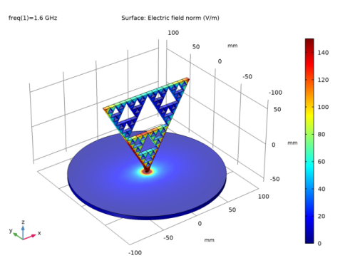
10 dB. Additional matching parts are not required for using the antenna at the higher-order resonances with the given fractal structure. The E-field norm plot on the PEC surface in Figure 2 describes the hotspot, about a quarter-wavelength, corresponding to its resonant frequency.
Figure 2: The visualized E-field on the radiator shows the hotspot at the 2nd resonance.
Figure 3: 3D far-field radiation pattern at the 2nd resonance. Some distortion at the lower half space is observed due to the ground plane.
Application Library path: RF_Module/Antennas/sierpinski_fractal_monopole_antenna
Modeling Instructions
From the File menu, choose New.
New
In the New window, click  Model Wizard.
Model Wizard
1
In the Model Wizard window, click  3D.
2
In the Select Physics tree, select Radio Frequency>Electromagnetic Waves, Frequency Domain (emw).
3
Click Add.
4
Click  Study.
5
In the Select Study tree, select General Studies>Frequency Domain.
6
Study 1
Step 1: Frequency Domain
1
In the Model Builder window, under Study 1 click Step 1: Frequency Domain.
2
In the Settings window for Frequency Domain, locate the Study Settings section.
3
In the Frequencies text field, type 1.6[GHz] 3[GHz].
Global Definitions
Parameters 1
1
In the Model Builder window, under Global Definitions click Parameters 1.
2
In the Settings window for Parameters, locate the Parameters section.
3
Click  Load from File.
4
Geometry 1
1
In the Model Builder window, under Component 1 (comp1) click Geometry 1.
2
In the Settings window for Geometry, locate the Units section.
3
From the Length unit list, choose mm.
Start by activating wireframe rendering to get a better view of the coaxial cable parts which are inside the ground plane.
4
Click the  Wireframe Rendering button in the Graphics toolbar.
Create a cylinder for the ground plane.
Ground plane
1
In the Geometry toolbar, click  Cylinder.
2
In the Settings window for Cylinder, type Ground plane in the Label text field.
3
Locate the Size and Shape section. In the Radius text field, type 100.
4
In the Height text field, type thickness.
5
Locate the Position section. In the z text field, type -55.
Add two cylinders for the inner outer conductor of the coaxial cable.
Coax inner
1
In the Geometry toolbar, click  Cylinder.
2
In the Settings window for Cylinder, type Coax inner in the Label text field.
3
Locate the Size and Shape section. In the Radius text field, type r_inner.
4
In the Height text field, type thickness+2.
5
Locate the Position section. In the z text field, type -55.
Coax outer
1
In the Geometry toolbar, click  Cylinder.
2
In the Settings window for Cylinder, type Coax outer in the Label text field.
3
Locate the Size and Shape section. In the Radius text field, type r_outer.
4
In the Height text field, type thickness.
5
Locate the Position section. In the z text field, type -55.
6
Click  Build Selected.
Add a sphere for the PML. Use the layer definition to create a shell type structure.
PMLs
1
In the Geometry toolbar, click  Sphere.
2
In the Settings window for Sphere, type PMLs in the Label text field.
3
Locate the Size section. In the Radius text field, type 180[mm].
4
Click to expand the Layers section. In the table, enter the following settings:
Next, add a work plane where you will create the Sierpinski fractal triangle.
Work Plane 1 (wp1)
1
In the Geometry toolbar, click  Work Plane.
2
In the Settings window for Work Plane, locate the Plane Definition section.
3
From the Plane list, choose zx-plane.
4
In the y-coordinate text field, type -thickness/2.
5
Click  Show Work Plane.
Work Plane 1 (wp1)>Plane Geometry
Use polygon to create a triangle. The initial triangle is not equilateral but isosceles to get integer numbers on the grid for easier and simpler copy operations.
Work Plane 1 (wp1)>Polygon 1 (pol1)
1
In the Work Plane toolbar, click  Polygon.
2
Click the  Zoom Extents button in the Graphics toolbar.
3
In the Settings window for Polygon, locate the Coordinates section.
4
5
Click  Build Selected.
6
Click the  Zoom In button in the Graphics toolbar, a couple of times.
This triangle is a seed object for the Sierpinski fractal triangle. Use Copy and Union repeatedly as shown below until it reaches 3rd order.
Work Plane 1 (wp1)>Copy 1 (copy1)
1
In the Work Plane toolbar, click  Transforms and choose Copy.
2
3
In the Settings window for Copy, locate the Displacement section.
4
In the xw text field, type 7,7.
5
In the yw text field, type 4,-4.
Work Plane 1 (wp1)>Union 1 (uni1)
1
In the Work Plane toolbar, click  Booleans and Partitions and choose Union.
2
Click in the Graphics window and then press Ctrl+A to select all objects.
3
In the Settings window for Union, click  Build Selected.
Work Plane 1 (wp1)>Copy 2 (copy2)
1
In the Work Plane toolbar, click  Transforms and choose Copy.
2
3
In the Settings window for Copy, locate the Displacement section.
4
In the xw text field, type 14,14.
5
In the yw text field, type 8,-8.
Work Plane 1 (wp1)>Union 2 (uni2)
1
In the Work Plane toolbar, click  Booleans and Partitions and choose Union.
2
Click in the Graphics window and then press Ctrl+A to select all objects.
3
In the Settings window for Union, click  Build Selected.
Work Plane 1 (wp1)>Copy 3 (copy3)
1
In the Work Plane toolbar, click  Transforms and choose Copy.
2
3
In the Settings window for Copy, locate the Displacement section.
4
In the xw text field, type 28,28.
5
In the yw text field, type 16,-16.
Work Plane 1 (wp1)>Union 3 (uni3)
1
In the Work Plane toolbar, click  Booleans and Partitions and choose Union.
2
Click in the Graphics window and then press Ctrl+A to select all objects.
3
In the Settings window for Union, click  Build Selected.
Work Plane 1 (wp1)>Copy 4 (copy4)
1
In the Work Plane toolbar, click  Transforms and choose Copy.
2
3
In the Settings window for Copy, locate the Displacement section.
4
In the xw text field, type 56,56.
5
In the yw text field, type 32,-32.
6
Click the  Zoom Out button in the Graphics toolbar.
7
Click  Build Selected.
This is the 3rd-order Sierpinski fractal triangle.
Work Plane 1 (wp1)>Plane Geometry
Add a polygon on the 1st triangle. The flat end is preferred to connect the coaxial pin (inner conductor).
Work Plane 1 (wp1)>Polygon 2 (pol2)
1
In the Work Plane toolbar, click  Polygon.
2
In the Settings window for Polygon, locate the Coordinates section.
3
Work Plane 1 (wp1)>Union 4 (uni4)
1
In the Work Plane toolbar, click  Booleans and Partitions and choose Union.
2
Click in the Graphics window and then press Ctrl+A to select all objects.
3
In the Settings window for Union, locate the Union section.
4
Clear the Keep interior boundaries check box.
5
Click  Build Selected.
Work Plane 1 (wp1)>Plane Geometry
Scale the entire triangle structure to generate equilateral triangles.
Work Plane 1 (wp1)>Scale 1 (sca1)
1
In the Work Plane toolbar, click  Transforms and choose Scale.
2
3
In the Settings window for Scale, locate the Scale Factor section.
4
From the Scaling list, choose Anisotropic.
5
In the xw text field, type 1/1.75*sqrt(3).
6
Locate the Center of Scaling section. In the xw text field, type -48.
Extrude 1 (ext1)
1
In the Model Builder window, under Component 1 (comp1)>Geometry 1 right-click Work Plane 1 (wp1) and choose Extrude.
2
In the Settings window for Extrude, locate the Distances section.
3
4
Click  Build All Objects.
The finished geometry represents the Sierpinski fractal monopole antenna inside the PML.
Definitions
Create a set of selections before setting up the physics. Add a selection for the domains that are not part of the model analysis. These are the inside domains of the fractal radiator and ground plane. Because these parts are modeled as PECs, the inside does not need to be analyzed.
Excluded
1
In the Definitions toolbar, click  Explicit.
2
In the Settings window for Explicit, type Excluded in the Label text field.
3
Locate the Input Entities section. Click  Paste Selection.
4
In the Paste Selection dialog box, type 6-47, 49-50, 53-56, 59-94 in the Selection text field.
5
Add a selection for the model domain. Use the complement of the Excluded domain.
Model space
1
In the Definitions toolbar, click  Complement.
2
In the Settings window for Complement, type Model space in the Label text field.
3
Locate the Input Entities section. Under Selections to invert, click  Add.
4
In the Add dialog box, select Excluded in the Selections to invert list.
5
Perfectly Matched Layer 1 (pml1)
1
In the Definitions toolbar, click  Perfectly Matched Layer.
2
3
In the Settings window for Perfectly Matched Layer, locate the Geometry section.
4
From the Type list, choose Spherical.
View 1
Suppress three domains to get a better view when setting up the physics and reviewing the meshed results.
Hide for Physics 1
1
In the Model Builder window, right-click View 1 and choose Hide for Physics.
2
Electromagnetic Waves, Frequency Domain (emw)
Now set up the physics. Use the model domain selection for the current physics. The boundaries of excluded domains will be set to perfect electric conductor by default.
1
In the Model Builder window, under Component 1 (comp1) click Electromagnetic Waves, Frequency Domain (emw).
2
In the Settings window for Electromagnetic Waves, Frequency Domain, locate the Domain Selection section.
3
From the Selection list, choose Model space.
Locate the coaxial lumped port on the bottom of the outer conductor. Zoom in a couple of times to get a clear view of the coaxial cable.
Lumped Port 1
1
In the Physics toolbar, click  Boundaries and choose Lumped Port.
2
Click the  Zoom In button in the Graphics toolbar.
3
4
In the Settings window for Lumped Port, locate the Lumped Port Properties section.
5
From the Type of lumped port list, choose Coaxial.
For the first port, wave excitation is on by default.
6
Click the  Zoom Extents button in the Graphics toolbar.
Far-Field Domain 1
In the Physics toolbar, click  Domains and choose Far-Field Domain.
Materials
Assign material properties. First, use air for all domains.
Add Material
1
In the Home toolbar, click  Add Material to open the Add Material window.
2
Go to the Add Material window.
3
4
Click Add to Component in the window toolbar.
5
In the Home toolbar, click  Add Material to close the Add Material window.
Materials
Override the substrate with the dielectric material of εr = 2.1.
PTFE
1
In the Model Builder window, under Component 1 (comp1) right-click Materials and choose Blank Material.
2
In the Settings window for Material, type PTFE in the Label text field.
3
4
Locate the Material Contents section. In the table, enter the following settings:
Mesh 1
1
In the Model Builder window, under Component 1 (comp1) click Mesh 1.
2
In the Settings window for Mesh, locate the Physics-Controlled Mesh section.
3
From the Element size list, choose Fine.
4
Click  Build All.
5
Click the  Zoom In button in the Graphics toolbar.
Study 1
1
In the Model Builder window, click Study 1.
2
In the Settings window for Study, locate the Study Settings section.
3
Clear the Generate default plots check box.
4
In the Home toolbar, click  Compute.
Results
Begin the result analysis by evaluating the S-parameters.
Global Evaluation 1
1
In the Model Builder window, expand the Results node.
2
Right-click Results>Derived Values and choose Global Evaluation.
3
In the Settings window for Global Evaluation, click Replace Expression in the upper-right corner of the Expressions section. From the menu, choose Component 1 (comp1)>Electromagnetic Waves, Frequency Domain>Ports>emw.S11dB - S11.
4
Click  Evaluate.
Table
1
Go to the Table window.
The calculated S-parameters for both frequencies are less than -10 dB.
Add a surface plot for the E-field norm. Before adding the surface plot, add a selection on the solution to specify the visualization area.
Results
Study 1/Solution 1 (sol1)
In the Model Builder window, expand the Results>Datasets node, then click Study 1/Solution 1 (sol1).
Selection
1
In the Results toolbar, click  Attributes and choose Selection.
2
In the Settings window for Selection, locate the Geometric Entity Selection section.
3
From the Geometric entity level list, choose Domain.
4
From the Selection list, choose Excluded.
3D Plot Group 1
1
In the Results toolbar, click  3D Plot Group.
2
In the Settings window for 3D Plot Group, locate the Data section.
3
From the Parameter value (freq (GHz)) list, choose 1.6.
Surface 1
1
Right-click 3D Plot Group 1 and choose Surface.
2
In the Settings window for Surface, click to expand the Range section.
3
Select the Manual color range check box.
4
In the Maximum text field, type 150.
5
In the 3D Plot Group 1 toolbar, click  Plot.
Compare the plot with Figure 2.
3D Plot Group 2
1
In the Home toolbar, click  Add Plot Group and choose 3D Plot Group.
2
In the Settings window for 3D Plot Group, locate the Plot Settings section.
3
Clear the Plot dataset edges check box.
4
Locate the Data section. From the Parameter value (freq (GHz)) list, choose 1.6.
Radiation Pattern 1
1
In the 3D Plot Group 2 toolbar, click  More Plots and choose Radiation Pattern.
2
In the Settings window for Radiation Pattern, locate the Evaluation section.
3
Find the Angles subsection. In the Number of elevation angles text field, type 60.
4
In the Number of azimuth angles text field, type 60.
5
In the 3D Plot Group 2 toolbar, click  Plot.
6
Click the  Zoom Extents button in the Graphics toolbar.
Compare this plot with that shown in Figure 3.