PDF

Chlorine Discharge Global Model
Introduction
Plasma discharges containing Chlorine are commonly used to etch semiconductors and metals in microelectronics fabrication. Cl2 has low dissociation energy and very low threshold energy for dissociative attachment, and atomic chlorine has large electron affinity. As a consequence a Cl2 plasma has substantial levels of electronegativity and dissociation. Quantification of the negative ion and atomic chlorine density is important to understand the reactor operation. In particular Chlorine atoms are accepted to be a main reactant for plasma etching.
In this study are presented model results of chlorine and electron density for absorbed powers between 25 and 600 W and for working pressures between 1 and 100 mTorr. To explore such a large parametric region it is used a global (volume-averaged) model since it can run simulations in a fraction of the time of a space dependent model while retaining the tendencies of volume-averaged physical quantities.
Model results of several relevant quantities such as atomic chlorine density, electron density, and electron temperature are in good agreement with measurements performed in inductively coupled plasma reactors found in the literature.
The reader can find more information about global models and Chlorine plasmas in Ref. 1, Ref. 2, and Ref. 3 and in the references therein.
Model Definition
The model used in this work considers that the spatial information of the different quantities in the plasma reactor can be treated as uniform or can be introduced using analytic models. Without the spatial derivatives the numerical solution of the equation set becomes considerably simpler and the computational time is reduced. In the following it is taken advantage of the fast computational time to investigate a broad region of parameters with a complex plasma chemistry.
When using a plasma global model the species densities and the electron temperature are treated as volume-averaged quantities. Detailed information on the global model can be found in the section Theory for Global Models in the Plasma Module User’s Guide. For heavy species the following equation is solved for the mass fraction
where ρ is the mass density (SI unit: kg/m3), wk is the mass fraction, wf,k is the mass fraction in the feed, mf and mo are the mass-flow rates of the total feed and outlet, and Rk is the rate expression (SI unit: kg/(m3·s)). The fourth term on the right-hand side accounts for surface losses and creation, where Al is the surface area, hl is a dimensionless correction term, V is the reactor volume, Mk is the species molar mass (SI unit: kg/mol) and Rsurf,k,l is the surface rate expression (SI unit: mol/(m2·s)) at a surface l. The last term is introduced because the species mass balance equations are written in the nonconservative form and it used the mass-continuity equation to replace for the mass density time derivative. In the last term Mf,l is the inward mass flux of surface l (SI unit: kg/(m2·s)). The sum in the last two terms is over all surfaces where there are surface reactions.
To take into account possible variations of the system total mass or pressure the mass-continuity equation can also be solved
.
The electron number density is obtained from electroneutrality
and if using the local energy approximation (LEA) the electron energy density nε (unit: V/ m3) is computed from
where Rε is the electron energy loss due to inelastic and elastic collisions, Pabs is the power absorbed by the electrons (SI unit: W), and e is the elementary charge. The last term on the right side accounts for the kinetic energy transported to the surface by electrons and ions. The summation is over all positive ions, εe is the mean kinetic energy lost per electron lost, εi is the mean kinetic energy lost per ion lost, and Na is Avogadro’s number. If using the local field approximation (LFA) the electron mean energy equation is not solved and the electron mean energy can be: (i) provided as a function of the electric field; or (ii) obtained by solving the Boltzmann equation in the two-term approximation.
The rate coefficients for electron impact reactions can be computed by appropriate averaging of cross sections over a EEDF. The EEDF can be either analytic or can be obtained by solving the steady state Boltzmann equation in the two-term approximation coupled with the equation system (The Boltzmann Equation, Two-Term Approximation Interface in the Plasma Module User’s Guide). When solving for the EEDF the coupling between the equations is as follows: (i) if the LEA is used the electron mean energy obtained from the electron mean energy equation is given as input to the Boltzmann solver; (ii) if the LFA is used the reduce electric field must be given as input to the Boltzmann solver and the electron mean energy comes from averaging over the computed EEDF.
This study uses the LEA and a Maxwellian EEDF to computed the electron impact rate coefficients.
In this work are simulated cylindrical reactors with several dimensions corresponding to inductively coupled plasma reactors used by different experimental groups. The simulations are performed for a reactor operating at constant pressure. Moreover, the mass-flow rate of the outlet is found by assuming that the feed and the surface reactions cannot change the total mass of the system
.
Note that the surface reactions used in these simulations do not change the mass of the system.
However the mass-continuity equation is not solved, the mass density can still change as a result of a change in the mean molar mass, thus accounting for changes in the number density (due to dissociation and association) to maintaining a constant pressure.
The expressions used for the mean kinetic energy lost per electron lost and the mean kinetic energy lost per ion lost are deduced from theory and numerical solution and are explained in Ref. 1and references therein. The gas temperature is a function of pressure and absorbed power and is based on experimental data Ref. 1.
plasma chemistry
It is used the plasma chemistry suggested in Ref. 2 and presented in Table 1that consists of 10 species and 44 reactions.
*The reaction set includes the inverse reaction with the rate coefficient obtained by detailed balance.
The model also include the surface reactions presented in Table 2.
The rate at which positive ions are lost to the wall is computed from the Bohm velocity and the density that an ion have near the surface. The ion density at the surface is estimated from theory Ref. 1 and Ref. 3 and is introduced in the model using the correction factor hl. Negative ions are assumed to be confined in the plasma bulk.
The rate at which neutral species are lost to the wall involves the information of diffusional losses, of the particle mean velocity, and of the sticking coefficient Ref. 1 and Ref. 3. The wall recombination of neutral chlorine atoms is an important aspect of chlorine containing discharges since it influences the degree of dissociation of the discharge. The sticking coefficient for the recombination of Cl at the surface is obtained by fitting experimental data Ref. 1. All other neutral excited species revert to ground state with sticking coefficient equal to one.
Results and Discussion
In this section are presented simulations results that can be compared with measurements and simulations reported in Ref. 1. The measurements are for inductively coupled plasma reactors with radius R and length L, operate at a given volumetric flow (Qf), and sweep either the input power or the pressure. The power absorbed by the plasma that is used in the simulations is estimated in Ref. 1. The parameters used in the simulations are summarized in Table 3, and are labeled with the name of the authors that perform the measurements. Overall the numeric results are consistent with those of Ref. 1 and agree well for most experimental conditions.
Corr et al
Figure 1 and Figure 2 present electron and Cl number density as a function of the absorbed power for the experimental conditions of Corr et al and Malyshev and Donnelly. The atomic Chlorine density for the conditions of Corr et al and the electron density for the conditions of Malyshev and Donnelly (Figure 2) agree well with measurements. The electron density for the conditions of Corr et al (Figure 1) is highly overestimated when compared with measurements but is consistent with the simulation results of Ref. 1. The electronegativity, also presented in Figure 1, only agrees well with measurements at higher absorbed powers.
Figure 3 presents electron and Cl number density as a function of the reactor pressure for the experimental conditions of Corr and others. There is a fair agreement for all conditions with the model capturing the tendencies but slightly underestimating the Cl density and overestimating the electron density.
Figure 4 presents the electron temperature as a function of the reactor pressure for the experimental conditions of Efremov and others. The model agrees well with measurements capturing the decrease of the electron temperature with pressure. However, the measured temperature decreases at a faster rate with pressure at higher pressures.
Figure 1: Model results for the electron and Cl densities, and for the electronegativity as a function of the absorbed power for the conditions of Corr et al: P=10 mTorr, Qf=10 sccm, R=10 cm, and L=8.5 cm.
Figure 2: Model results for the electron and Cl densities as a function of the absorbed power for the conditions of Malyshev and Donnelly: P=10 mTorr, Qf=100 sccm, R=8.5 cm, and L=20 cm.
Figure 3: Model results for the electron and Cl densities as a function of pressure. The Cl density is for the conditions of Corr et al: Pabs=300 W, Qf=10 sccm, R=10 cm, and L=8.5 cm. The electron density is for the conditions of Efremov et al: Pabs=300 W, Qf=20 sccm, R=25 cm, and L=14 cm.
Figure 4: Model results for the electron temperature as a function of pressure for the conditions of Efremov et al: Pabs=300 W and Qf=20 sccm, R=15 cm, and L=14 cm.
References
1. E.G. Thorsteinsson, and J.T. Gudmundsson, “A global (volume averaged) model of a chlorine discharge,” Plasma Sources Sci. Technol., vol. 19, p. 015001 (15pp), 2010.
2. E. Kemaneci, E. Carbone, J-P. Booth, W. Graef, J. van Dijk, and G. Kroesen, “Global (volume-averaged) model of inductively coupled chlorine plasma: influence of Cl wall recombination and external heating on continuous and pulse-modulated plasmas,” Plasma Sources Sci. Technol., vol. 23, p. 045002 (14pp), 2014.
3. M.A. Lieberman and A.J. Lichtenberg, Principles of Plasma Discharges and Materials Processing, John Wiley & Sons, 2005.
Application Library path: Plasma_Module/Global_Modeling/chlorine_global_model
Modeling Instructions
From the File menu, choose New.
New
In the New window, click  Model Wizard.
Model Wizard
1
In the Model Wizard window, click  2D Axisymmetric.
2
In the Select Physics tree, select Plasma>Plasma (plas).
3
Click Add.
4
Click  Study.
5
In the Select Study tree, select General Studies>Time Dependent.
6
Root
Construct a cylindrical reactor with radius Rad and length L. The values of Rad and L are set in the Parameters node.
Geometry 1
Rectangle 1 (r1)
1
In the Geometry toolbar, click  Rectangle.
2
In the Settings window for Rectangle, locate the Size and Shape section.
3
In the Width text field, type Rad.
4
In the Height text field, type L.
Global Definitions
Add parameters to be used in the simulations. The pressure and absorbed power need to be set here to be available to do a parameter sweep.
The different studies performed use different parameters so that before each new study (after the first study) it is necessary to change some of the parameters values.
Parameters 1
1
In the Model Builder window, under Global Definitions click Parameters 1.
2
In the Settings window for Parameters, locate the Parameters section.
3
Definitions
Import the file containing the energy levels to be used when defining the reactions.
Variables 1
1
In the Model Builder window, under Component 1 (comp1) right-click Definitions and choose Variables.
2
In the Settings window for Variables, locate the Variables section.
3
Click  Load from File.
4
Import the file containing the variables used to define the gas temperature, the plasma and sheath potential, and the hl correction factors.
Variables 2
1
In the Model Builder window, right-click Definitions and choose Variables.
2
In the Settings window for Variables, locate the Variables section.
3
Click  Load from File.
4
Choose to use a global model for the following simulations and set the model to work at constant pressure.
Plasma (plas)
1
In the Model Builder window, under Component 1 (comp1) click Plasma (plas).
2
In the Settings window for Plasma, locate the Diffusion Model section.
3
From the Diffusion model list, choose Global.
4
Locate the Reactor section. From the Reactor type list, choose Constant pressure.
Set the background gas temperature, the working pressure, the total mass flow, the power absorbed, the mean kinetic energy lost per ion and electron lost.
The mole fraction of each species in the mass flow is set later in the species node.
Plasma Model 1
1
In the Model Builder window, under Component 1 (comp1)>Plasma (plas) click Plasma Model 1.
2
In the Settings window for Plasma Model, locate the Model Inputs section.
3
In the T text field, type Th.
4
In the pA text field, type p0.
5
Locate the Total Mass Flow section. In the Qsccm text field, type Qfeed.
6
Locate the Mean Electron Energy Specification section. In the Pabs text field, type Pabs.
7
In the εe text field, type Epsilon_e.
8
In the εi text field, type Epsilon_p+Epsilon_s.
Add reactions relevant for the Chlorine plasma chemistry. There are about 40 volume reactions that need to be added.
For electron impact reactions it is needed to set the collision type, the rate constant and the energy loss in the collision.
For reactions between heavy species it is only necessary to set the rate constant.
Electron Impact Reaction 1
1
In the Physics toolbar, click  Domains and choose Electron Impact Reaction.
2
In the Settings window for Electron Impact Reaction, locate the Reaction Formula section.
3
In the Formula text field, type e+Cl2=>Cl+Cl+e.
4
Locate the Collision Type section. From the Collision type list, choose Excitation.
5
In the Δε text field, type ediss.
6
Locate the Reaction Parameters section. In the kf text field, type 1.04e-13*plas.Te^(-0.29)*exp(-8.84/plas.Te)*N_A_const.
Electron Impact Reaction 2
1
In the Physics toolbar, click  Domains and choose Electron Impact Reaction.
2
In the Settings window for Electron Impact Reaction, locate the Reaction Formula section.
3
In the Formula text field, type e+Cl2=>2e+Cl2+.
4
Locate the Collision Type section. From the Collision type list, choose Ionization.
5
In the Δε text field, type eionCl2.
6
Locate the Reaction Parameters section. In the kf text field, type 5.12e-14*plas.Te^(0.48)*exp(-12.34/plas.Te)*N_A_const.
Electron Impact Reaction 3
1
In the Physics toolbar, click  Domains and choose Electron Impact Reaction.
2
In the Settings window for Electron Impact Reaction, locate the Reaction Formula section.
3
In the Formula text field, type e+Cl2=>2e+Cl+Cl+.
4
Locate the Collision Type section. From the Collision type list, choose Ionization.
5
In the Δε text field, type eionCl.
6
Locate the Reaction Parameters section. In the kf text field, type 2.14e-13*plas.Te^(-0.07)*exp(-25.26/plas.Te)*N_A_const.
Electron Impact Reaction 4
1
In the Physics toolbar, click  Domains and choose Electron Impact Reaction.
2
In the Settings window for Electron Impact Reaction, locate the Reaction Formula section.
3
In the Formula text field, type e+Cl2=>3e+2Cl+.
4
Locate the Collision Type section. From the Collision type list, choose Ionization.
5
In the Δε text field, type 2*eionCl.
6
Locate the Reaction Parameters section. In the kf text field, type 2.27e-16*plas.Te^(1.92)*exp(-21.26/plas.Te)*N_A_const.
Electron Impact Reaction 5
1
In the Physics toolbar, click  Domains and choose Electron Impact Reaction.
2
In the Settings window for Electron Impact Reaction, locate the Reaction Formula section.
3
In the Formula text field, type e+Cl2=>Cl+Cl-.
4
Locate the Collision Type section. From the Collision type list, choose Attachment.
5
Locate the Reaction Parameters section. In the kf text field, type (3.43e-15*plas.Te^(-1.18)*exp(-3.98/plas.Te) + 3.05e-16*plas.Te^(-1.33)*exp(-0.11/(plas.Te+0.014)))*N_A_const.
Electron Impact Reaction 6
1
In the Physics toolbar, click  Domains and choose Electron Impact Reaction.
2
In the Settings window for Electron Impact Reaction, locate the Reaction Formula section.
3
In the Formula text field, type e+Cl2v1=>Cl+Cl-.
4
Locate the Collision Type section. From the Collision type list, choose Attachment.
5
Locate the Reaction Parameters section. In the kf text field, type (14.06e-15*plas.Te^(-1.18)*exp(-3.98/plas.Te) + 12.51e-16*plas.Te^(-1.33)*exp(-0.11/(plas.Te+0.014)))*N_A_const.
Electron Impact Reaction 7
1
In the Physics toolbar, click  Domains and choose Electron Impact Reaction.
2
In the Settings window for Electron Impact Reaction, locate the Reaction Formula section.
3
In the Formula text field, type e+Cl2v2=>Cl+Cl-.
4
Locate the Collision Type section. From the Collision type list, choose Attachment.
5
Locate the Reaction Parameters section. In the kf text field, type (30.18e-15*plas.Te^(-1.18)*exp(-3.98/plas.Te) + 26.84e-16*plas.Te^(-1.33)*exp(-0.11/(plas.Te+0.014)))*N_A_const.
Electron Impact Reaction 8
1
In the Physics toolbar, click  Domains and choose Electron Impact Reaction.
2
In the Settings window for Electron Impact Reaction, locate the Reaction Formula section.
3
In the Formula text field, type e+Cl2v3=>Cl+Cl-.
4
Locate the Collision Type section. From the Collision type list, choose Attachment.
5
Locate the Reaction Parameters section. In the kf text field, type (46.31e-15*plas.Te^(-1.18)*exp(-3.98/plas.Te) + 41.18e-16*plas.Te^(-1.33)*exp(-0.11/(plas.Te+0.014)))*N_A_const.
Electron Impact Reaction 9
1
In the Physics toolbar, click  Domains and choose Electron Impact Reaction.
2
In the Settings window for Electron Impact Reaction, locate the Reaction Formula section.
3
In the Formula text field, type e+Cl2=>Cl++Cl-+e.
4
Locate the Collision Type section. From the Collision type list, choose Excitation.
5
In the Δε text field, type eionCl.
6
Locate the Reaction Parameters section. In the kf text field, type 2.94e-16*plas.Te^(0.19)*exp(-18.79/plas.Te)*N_A_const.
Electron Impact Reaction 10
1
In the Physics toolbar, click  Domains and choose Electron Impact Reaction.
2
In the Settings window for Electron Impact Reaction, locate the Reaction Formula section.
3
In the Formula text field, type e+Cl2=>e+Cl2v1.
4
Locate the Collision Type section. From the Collision type list, choose Excitation.
5
In the Δε text field, type ev1.
6
Locate the Reaction Parameters section. In the kf text field, type 3.99e-12*plas.Te^(-1.5)*exp(-7.51/plas.Te-0.0001/plas.Te^2)*N_A_const.
Electron Impact Reaction 11
1
In the Physics toolbar, click  Domains and choose Electron Impact Reaction.
2
In the Settings window for Electron Impact Reaction, locate the Reaction Formula section.
3
In the Formula text field, type e+Cl2=>e+Cl2v2.
4
Locate the Collision Type section. From the Collision type list, choose Excitation.
5
In the Δε text field, type ev2.
6
Locate the Reaction Parameters section. In the kf text field, type (3.28e-17*plas.Te^(-1.12)*exp(-0.37/plas.Te) + 2.86e-17*exp(-(log(plas.Te)+0.99)^2/(2*1.06^2)))*N_A_const.
Electron Impact Reaction 12
1
In the Physics toolbar, click  Domains and choose Electron Impact Reaction.
2
In the Settings window for Electron Impact Reaction, locate the Reaction Formula section.
3
In the Formula text field, type e+Cl2=>e+Cl2v3.
4
Locate the Collision Type section. From the Collision type list, choose Excitation.
5
In the Δε text field, type ev3.
6
Locate the Reaction Parameters section. In the kf text field, type (1.3e-17*plas.Te^(-1.24)*exp(-0.41/plas.Te) + 6.08e-18*exp(-(log(plas.Te)+0.94)^2/(2*1.02^2)))*N_A_const.
Electron Impact Reaction 13
1
In the Physics toolbar, click  Domains and choose Electron Impact Reaction.
2
In the Settings window for Electron Impact Reaction, locate the Reaction Formula section.
3
In the Formula text field, type e+Cl2v1=>e+Cl2v2.
4
Locate the Collision Type section. From the Collision type list, choose Excitation.
5
In the Δε text field, type ev2-ev1.
6
Locate the Reaction Parameters section. In the kf text field, type (3e-16*plas.Te^(-1.0)*exp(-0.37/plas.Te) + 4.61e-16*exp(-(log(plas.Te)+1.04)^2/(2*1.10^2)))*N_A_const.
Electron Impact Reaction 14
1
In the Physics toolbar, click  Domains and choose Electron Impact Reaction.
2
In the Settings window for Electron Impact Reaction, locate the Reaction Formula section.
3
In the Formula text field, type e+Cl2v2=>e+Cl2v3.
4
Locate the Collision Type section. From the Collision type list, choose Excitation.
5
In the Δε text field, type ev3-ev2.
6
Locate the Reaction Parameters section. In the kf text field, type (3e-16*plas.Te^(-1.0)*exp(-0.37/plas.Te) + 4.61e-16*exp(-(log(plas.Te)+1.04)^2/(2*1.10^2)))*N_A_const.
Electron Impact Reaction 15
1
In the Physics toolbar, click  Domains and choose Electron Impact Reaction.
2
In the Settings window for Electron Impact Reaction, locate the Reaction Formula section.
3
In the Formula text field, type e+Cl2v1=>e+Cl2v3.
4
Locate the Collision Type section. From the Collision type list, choose Excitation.
5
In the Δε text field, type ev3-ev1.
6
Locate the Reaction Parameters section. In the kf text field, type (1.25e-16*plas.Te^(-1.13)*exp(-0.36/plas.Te) + 1.06e-16*exp(-(log(plas.Te)+1.01)^2/(2*1.06^2)))*N_A_const.
Electron Impact Reaction 16
1
In the Physics toolbar, click  Domains and choose Electron Impact Reaction.
2
In the Settings window for Electron Impact Reaction, locate the Reaction Formula section.
3
In the Formula text field, type e+Cl2+=>2Cl.
4
Locate the Collision Type section. From the Collision type list, choose Excitation.
5
In the Δε text field, type -eionCl2.
6
Locate the Reaction Parameters section. In the kf text field, type 9e-14*plas.Te^(-0.5)*N_A_const.
Electron Impact Reaction 17
1
In the Physics toolbar, click  Domains and choose Electron Impact Reaction.
2
In the Settings window for Electron Impact Reaction, locate the Reaction Formula section.
3
In the Formula text field, type e+Cl=>e+Cl12.
4
Locate the Collision Type section. From the Collision type list, choose Excitation.
5
In the Δε text field, type eCl12.
6
Locate the Reaction Parameters section. In the kf text field, type 4.55e-14*plas.Te^(-0.46)*exp(-2.01/plas.Te-0.001/plas.Te^2)*N_A_const.
Electron Impact Reaction 18
1
In the Physics toolbar, click  Domains and choose Electron Impact Reaction.
2
In the Settings window for Electron Impact Reaction, locate the Reaction Formula section.
3
In the Formula text field, type e+Cl=>e+Cl52.
4
Locate the Collision Type section. From the Collision type list, choose Excitation.
5
In the Δε text field, type eCl52.
6
Locate the Reaction Parameters section. In the kf text field, type (7.03e-17*plas.Te^(0.55)*exp(-2.15/plas.Te-1.5/plas.Te^2-2.05/plas.Te^3))*N_A_const.
Electron Impact Reaction 19
1
In the Physics toolbar, click  Domains and choose Electron Impact Reaction.
2
In the Settings window for Electron Impact Reaction, locate the Reaction Formula section.
3
In the Formula text field, type e+Cl=>Cl++2e.
4
Locate the Collision Type section. From the Collision type list, choose Ionization.
5
In the Δε text field, type eionCl.
6
Locate the Reaction Parameters section. In the kf text field, type 3.17e-14*plas.Te^(0.53)*exp(-13.29/plas.Te)*N_A_const.
Electron Impact Reaction 20
1
In the Physics toolbar, click  Domains and choose Electron Impact Reaction.
2
In the Settings window for Electron Impact Reaction, locate the Reaction Formula section.
3
In the Formula text field, type e+Cl12=>Cl++2e.
4
Locate the Collision Type section. From the Collision type list, choose Ionization.
5
In the Δε text field, type eionCl-eCl12.
6
Locate the Reaction Parameters section. In the kf text field, type 3.17e-14*plas.Te^(0.53)*exp(-13.29/plas.Te)*N_A_const.
Electron Impact Reaction 21
1
In the Physics toolbar, click  Domains and choose Electron Impact Reaction.
2
In the Settings window for Electron Impact Reaction, locate the Reaction Formula section.
3
In the Formula text field, type e+Cl52=>Cl++2e.
4
Locate the Collision Type section. From the Collision type list, choose Ionization.
5
In the Δε text field, type eionCl-eCl52.
6
Locate the Reaction Parameters section. In the kf text field, type (4.33e-14*plas.Te^(0.55)*exp(-0.15/plas.Te-0.85/plas.Te^2))*N_A_const.
Electron Impact Reaction 22
1
In the Physics toolbar, click  Domains and choose Electron Impact Reaction.
2
In the Settings window for Electron Impact Reaction, locate the Reaction Formula section.
3
In the Formula text field, type e+Cl-=>Cl+2e.
4
Locate the Collision Type section. From the Collision type list, choose Ionization.
5
In the Δε text field, type eatt.
6
Locate the Reaction Parameters section. In the kf text field, type 9.02e-15*plas.Te^(0.92)*exp(-4.88/plas.Te)*N_A_const.
Electron Impact Reaction 23
1
In the Physics toolbar, click  Domains and choose Electron Impact Reaction.
2
In the Settings window for Electron Impact Reaction, locate the Reaction Formula section.
3
In the Formula text field, type e+Cl-=>Cl++3e.
4
Locate the Collision Type section. From the Collision type list, choose Ionization.
5
In the Δε text field, type eatt+eionCl.
6
Locate the Reaction Parameters section. In the kf text field, type 3.62e-15*plas.Te^(0.72)*exp(-25.38/plas.Te)*N_A_const.
Electron Impact Reaction 24
1
In the Physics toolbar, click  Domains and choose Electron Impact Reaction.
2
In the Settings window for Electron Impact Reaction, locate the Reaction Formula section.
3
In the Formula text field, type e+Cl2v1=>e+Cl2.
4
Locate the Collision Type section. From the Collision type list, choose Excitation.
5
In the Δε text field, type -ev1.
6
Locate the Reaction Parameters section. In the kf text field, type 3.99e-12*plas.Te^(-1.5)*exp(-7.51/plas.Te-0.0001/plas.Te^2)*N_A_const*exp(ev1/plas.Te).
Electron Impact Reaction 25
1
In the Physics toolbar, click  Domains and choose Electron Impact Reaction.
2
In the Settings window for Electron Impact Reaction, locate the Reaction Formula section.
3
In the Formula text field, type e+Cl2v2=>e+Cl2.
4
Locate the Collision Type section. From the Collision type list, choose Excitation.
5
In the Δε text field, type -ev2.
6
Locate the Reaction Parameters section. In the kf text field, type (3.28e-17*plas.Te^(-1.12)*exp(-0.37/plas.Te) + 2.86e-17*exp(-(log(plas.Te)+0.99)^2/(2*1.06^2)))*N_A_const*exp(ev2/plas.Te).
Electron Impact Reaction 26
1
In the Physics toolbar, click  Domains and choose Electron Impact Reaction.
2
In the Settings window for Electron Impact Reaction, locate the Reaction Formula section.
3
In the Formula text field, type e+Cl2v3=>e+Cl2.
4
Locate the Collision Type section. From the Collision type list, choose Excitation.
5
In the Δε text field, type -ev3.
6
Locate the Reaction Parameters section. In the kf text field, type (1.3e-17*plas.Te^(-1.24)*exp(-0.41/plas.Te) + 6.08e-18*exp(-(log(plas.Te)+0.94)^2/(2*1.02^2)))*N_A_const*exp(ev3/plas.Te).
Electron Impact Reaction 27
1
In the Physics toolbar, click  Domains and choose Electron Impact Reaction.
2
In the Settings window for Electron Impact Reaction, locate the Reaction Formula section.
3
In the Formula text field, type e+Cl2v2=>e+Cl2v1.
4
Locate the Collision Type section. From the Collision type list, choose Excitation.
5
In the Δε text field, type -(ev2-ev1).
6
Locate the Reaction Parameters section. In the kf text field, type (3e-16*plas.Te^(-1.0)*exp(-0.37/plas.Te) + 4.61e-16*exp(-(log(plas.Te)+1.04)^2/(2*1.10^2)))*N_A_const*exp((ev2-ev1)/plas.Te).
Electron Impact Reaction 28
1
In the Physics toolbar, click  Domains and choose Electron Impact Reaction.
2
In the Settings window for Electron Impact Reaction, locate the Reaction Formula section.
3
In the Formula text field, type e+Cl2v3=>e+Cl2v2.
4
Locate the Collision Type section. From the Collision type list, choose Excitation.
5
In the Δε text field, type -(ev3-ev2).
6
Locate the Reaction Parameters section. In the kf text field, type (3e-16*plas.Te^(-1.0)*exp(-0.37/plas.Te) + 4.61e-16*exp(-(log(plas.Te)+1.04)^2/(2*1.10^2)))*N_A_const*exp((ev3-ev2)/plas.Te).
Electron Impact Reaction 29
1
In the Physics toolbar, click  Domains and choose Electron Impact Reaction.
2
In the Settings window for Electron Impact Reaction, locate the Reaction Formula section.
3
In the Formula text field, type e+Cl2v3=>e+Cl2v1.
4
Locate the Collision Type section. From the Collision type list, choose Excitation.
5
In the Δε text field, type -(ev3-ev1).
6
Locate the Reaction Parameters section. In the kf text field, type (1.25e-16*plas.Te^(-1.13)*exp(-0.36/plas.Te) + 1.06e-16*exp(-(log(plas.Te)+1.01)^2/(2*1.06^2)))*N_A_const*exp((ev3-ev1)/plas.Te).
Electron Impact Reaction 30
1
In the Physics toolbar, click  Domains and choose Electron Impact Reaction.
2
In the Settings window for Electron Impact Reaction, locate the Reaction Formula section.
3
In the Formula text field, type e+Cl12=>e+Cl.
4
Locate the Collision Type section. From the Collision type list, choose Excitation.
5
In the Δε text field, type -eCl12.
6
Locate the Reaction Parameters section. In the kf text field, type 4.55e-14*plas.Te^(-0.46)*exp(-2.01/plas.Te-0.001/plas.Te^2)*N_A_const*exp((eCl12)/plas.Te).
Electron Impact Reaction 31
1
In the Physics toolbar, click  Domains and choose Electron Impact Reaction.
2
In the Settings window for Electron Impact Reaction, locate the Reaction Formula section.
3
In the Formula text field, type e+Cl52=>e+Cl.
4
Locate the Collision Type section. From the Collision type list, choose Excitation.
5
In the Δε text field, type -eCl52.
6
Locate the Reaction Parameters section. In the kf text field, type (7.03e-17*plas.Te^(0.55)*exp(-2.15/plas.Te-1.5/plas.Te^2-2.05/plas.Te^3))*N_A_const*exp((eCl52)/plas.Te).
Reaction 1
1
In the Physics toolbar, click  Domains and choose Reaction.
2
In the Settings window for Reaction, locate the Reaction Formula section.
3
In the Formula text field, type Cl52=>Cl.
4
Locate the Reaction Parameters section. In the kf text field, type 1e5.
Reaction 2
1
In the Physics toolbar, click  Domains and choose Reaction.
2
In the Settings window for Reaction, locate the Reaction Formula section.
3
In the Formula text field, type Cl2++Cl-=>3Cl.
4
Locate the Reaction Parameters section. In the kf text field, type 5e-14*(300/Th)^0.5*N_A_const.
Reaction 3
1
In the Physics toolbar, click  Domains and choose Reaction.
2
In the Settings window for Reaction, locate the Reaction Formula section.
3
In the Formula text field, type Cl2++Cl-=>Cl+Cl2.
4
Locate the Reaction Parameters section. In the kf text field, type 5e-14[m^3/s]*N_A_const.
Reaction 4
1
In the Physics toolbar, click  Domains and choose Reaction.
2
In the Settings window for Reaction, locate the Reaction Formula section.
3
In the Formula text field, type Cl++Cl-=>2Cl.
4
Locate the Reaction Parameters section. In the kf text field, type 5e-14*(300/Th)^0.5*N_A_const.
Reaction 5
1
In the Physics toolbar, click  Domains and choose Reaction.
2
In the Settings window for Reaction, locate the Reaction Formula section.
3
In the Formula text field, type Cl2+Cl+=>Cl+Cl2+.
4
Locate the Reaction Parameters section. In the kf text field, type 5.4e-16[m^3/s]*N_A_const.
Reaction 6
1
In the Physics toolbar, click  Domains and choose Reaction.
2
In the Settings window for Reaction, locate the Reaction Formula section.
3
In the Formula text field, type Cl2v1+Cl+=>Cl+Cl2+.
4
Locate the Reaction Parameters section. In the kf text field, type 5.4e-16[m^3/s]*N_A_const.
Reaction 7
1
In the Physics toolbar, click  Domains and choose Reaction.
2
In the Settings window for Reaction, locate the Reaction Formula section.
3
In the Formula text field, type Cl2v2+Cl+=>Cl+Cl2+.
4
Locate the Reaction Parameters section. In the kf text field, type 5.4e-16[m^3/s]*N_A_const.
Reaction 8
1
In the Physics toolbar, click  Domains and choose Reaction.
2
In the Settings window for Reaction, locate the Reaction Formula section.
3
In the Formula text field, type Cl2v3+Cl+=>Cl+Cl2+.
4
Locate the Reaction Parameters section. In the kf text field, type 5.4e-16[m^3/s]*N_A_const.
Reaction 9
1
In the Physics toolbar, click  Domains and choose Reaction.
2
In the Settings window for Reaction, locate the Reaction Formula section.
3
In the Formula text field, type 2Cl+Cl2=>2Cl2.
4
Locate the Reaction Parameters section. In the kf text field, type 3.5e-45*exp(810/Th)*N_A_const.
Reaction 10
1
In the Physics toolbar, click  Domains and choose Reaction.
2
In the Settings window for Reaction, locate the Reaction Formula section.
3
In the Formula text field, type 2Cl+Cl=>Cl2+Cl.
4
Locate the Reaction Parameters section. In the kf text field, type 8.75e-46*exp(810/Th)*N_A_const.
Reaction 11
1
In the Physics toolbar, click  Domains and choose Reaction.
2
In the Settings window for Reaction, locate the Reaction Formula section.
3
In the Formula text field, type Cl+Cl2v3=>Cl+Cl2v2.
4
Locate the Reaction Parameters section. In the kf text field, type 1.3e-17*(Th/300)^0.5*N_A_const.
Reaction 12
1
In the Physics toolbar, click  Domains and choose Reaction.
2
In the Settings window for Reaction, locate the Reaction Formula section.
3
In the Formula text field, type Cl+Cl2v2=>Cl+Cl2v1.
4
Locate the Reaction Parameters section. In the kf text field, type 1.3e-17*(Th/300)^0.5*N_A_const.
Reaction 13
1
In the Physics toolbar, click  Domains and choose Reaction.
2
In the Settings window for Reaction, locate the Reaction Formula section.
3
In the Formula text field, type Cl+Cl2v1=>Cl+Cl2.
4
Locate the Reaction Parameters section. In the kf text field, type 1.3e-17*(Th/300)^0.5*N_A_const.
This model has two electron impact reactions of the elastic type: one with molecular Chlorine and another with atomic Chlorine.
These two reactions are defined using collision cross section data that needs to be imported from files.
Electron Impact Reaction 32
1
In the Physics toolbar, click  Domains and choose Electron Impact Reaction.
2
In the Settings window for Electron Impact Reaction, locate the Reaction Formula section.
3
In the Formula text field, type e+Cl2=>e+Cl2.
4
Locate the Collision Type section. In the mr text field, type 7.720e-6.
5
Locate the Collision section. From the Specify reaction using list, choose Cross-section data.
6
Locate the Reaction Parameters section. From the Electron energy distribution function list, choose Maxwellian.
7
Find the Collision cross section data subsection. Click  Load from File.
8
Electron Impact Reaction 33
1
In the Physics toolbar, click  Domains and choose Electron Impact Reaction.
2
In the Settings window for Electron Impact Reaction, locate the Reaction Formula section.
3
In the Formula text field, type e+Cl=>e+Cl.
4
Locate the Collision Type section. In the mr text field, type 1.510e-5.
5
Locate the Collision section. From the Specify reaction using list, choose Cross-section data.
6
Locate the Reaction Parameters section. From the Electron energy distribution function list, choose Maxwellian.
7
Find the Collision cross section data subsection. Click  Load from File.
8
In the species nodes (for heavy species) set the species data by choosing the atomic and molecular chlorine presets accordingly.
This information is used to compute the diffusion coefficients and the Bohm velocity that is used to estimate the surface losses of neutral species and positive ions, respectively.
Also for each species set the initial mole fraction (for neutrals) and the initial number density (for ions) in the reactor.
If the species is a neutral it is also possible to set the mole fraction of the total mass flow.
In this model the feed only contains molecular Chlorine so that the Feed mole fraction of Cl2 is set to 1.
Species: Cl2
1
In the Model Builder window, click Species: Cl2.
2
In the Settings window for Species, locate the Species Formula section.
3
Select the From mass constraint check box.
4
Locate the General Parameters section. From the Preset species data list, choose Cl2.
5
In the xfeed text field, type 1.
Species: Cl
1
In the Model Builder window, click Species: Cl.
2
In the Settings window for Species, locate the General Parameters section.
3
From the Preset species data list, choose Cl.
Species: Cl2+
1
In the Model Builder window, click Species: Cl2+.
2
In the Settings window for Species, locate the General Parameters section.
3
From the Preset species data list, choose Cl2.
4
In the n0 text field, type 1E16[1/m^3].
Species: Cl+
1
In the Model Builder window, click Species: Cl+.
2
In the Settings window for Species, locate the General Parameters section.
3
In the n0 text field, type 1E14[1/m^3].
4
From the Preset species data list, choose Cl.
Species: Cl-
1
In the Model Builder window, click Species: Cl-.
2
In the Settings window for Species, locate the General Parameters section.
3
From the Preset species data list, choose Cl.
4
In the n0 text field, type 1E14[1/m^3].
Species: Cl2v1
1
In the Model Builder window, click Species: Cl2v1.
2
In the Settings window for Species, locate the General Parameters section.
3
From the Preset species data list, choose Cl2.
Species: Cl2v2
1
In the Model Builder window, click Species: Cl2v2.
2
In the Settings window for Species, locate the General Parameters section.
3
From the Preset species data list, choose Cl2.
Species: Cl2v3
1
In the Model Builder window, click Species: Cl2v3.
2
In the Settings window for Species, locate the General Parameters section.
3
From the Preset species data list, choose Cl2.
Species: Cl12
1
In the Model Builder window, click Species: Cl12.
2
In the Settings window for Species, locate the General Parameters section.
3
From the Preset species data list, choose Cl.
Species: Cl52
1
In the Model Builder window, click Species: Cl52.
2
In the Settings window for Species, locate the General Parameters section.
3
From the Preset species data list, choose Cl.
Add surface reactions to estimate the losses at the walls.
Neutral species are estimated to be lost with the same frequency at all boundaries. In Contrast, the surface losses of positive ions in this model are different at radial and longitudinal boundaries.
For each ion two surface reactions are created: one selects longitudinal boundaries and sets the longitudinal correction factor, the other select the radial boundary and sets the radial correction factor.
Surface Reaction 1
1
In the Physics toolbar, click  Boundaries and choose Surface Reaction.
2
In the Settings window for Surface Reaction, locate the Reaction Formula section.
3
In the Formula text field, type Cl2+=>Cl2.
4
From the Specify reaction using list, choose Bohm velocity.
5
Locate the Reaction Parameters section. In the hl text field, type hRCl2.
6
Surface Reaction 2
1
In the Physics toolbar, click  Boundaries and choose Surface Reaction.
2
In the Settings window for Surface Reaction, locate the Reaction Formula section.
3
In the Formula text field, type Cl=>0.5Cl2.
4
From the Specify reaction using list, choose Sticking coefficient and diffusion.
5
Locate the Reaction Parameters section. In the γf text field, type gammaCl_steel.
6
In the Λeff text field, type Lambda_diff.
7
Locate the Boundary Selection section. From the Selection list, choose All boundaries.
Surface Reaction 3
1
In the Physics toolbar, click  Boundaries and choose Surface Reaction.
2
In the Settings window for Surface Reaction, locate the Reaction Formula section.
3
In the Formula text field, type Cl+=>Cl.
4
From the Specify reaction using list, choose Bohm velocity.
5
Locate the Reaction Parameters section. In the hl text field, type hRCl.
6
Surface Reaction 4
1
In the Physics toolbar, click  Boundaries and choose Surface Reaction.
2
In the Settings window for Surface Reaction, locate the Reaction Formula section.
3
In the Formula text field, type Cl2v1=>Cl2.
4
From the Specify reaction using list, choose Sticking coefficient and diffusion.
5
Locate the Reaction Parameters section. In the Λeff text field, type Lambda_diff.
6
Locate the Boundary Selection section. From the Selection list, choose All boundaries.
5: Cl2v1=>Cl2
1
Right-click Surface Reaction 4 and choose Duplicate.
2
In the Settings window for Surface Reaction, locate the Reaction Formula section.
3
In the Formula text field, type Cl2v2=>Cl2.
6: Cl2v2=>Cl2
1
Right-click 5: Cl2v1=>Cl2 and choose Duplicate.
2
In the Settings window for Surface Reaction, locate the Reaction Formula section.
3
In the Formula text field, type Cl2v3=>Cl2.
7: Cl2v3=>Cl2
1
Right-click 6: Cl2v2=>Cl2 and choose Duplicate.
2
In the Settings window for Surface Reaction, locate the Reaction Formula section.
3
In the Formula text field, type Cl12=>Cl.
8: Cl12=>Cl
1
Right-click 7: Cl2v3=>Cl2 and choose Duplicate.
2
In the Settings window for Surface Reaction, locate the Reaction Formula section.
3
In the Formula text field, type Cl52=>Cl.
Surface Reaction 9
1
In the Physics toolbar, click  Boundaries and choose Surface Reaction.
2
In the Settings window for Surface Reaction, locate the Reaction Formula section.
3
In the Formula text field, type Cl2+=>Cl2.
4
From the Specify reaction using list, choose Bohm velocity.
5
Locate the Reaction Parameters section. In the hl text field, type hLCl2.
6
Surface Reaction 10
1
In the Physics toolbar, click  Boundaries and choose Surface Reaction.
2
In the Settings window for Surface Reaction, locate the Reaction Formula section.
3
In the Formula text field, type Cl+=>Cl.
4
From the Specify reaction using list, choose Bohm velocity.
5
Locate the Reaction Parameters section. In the hl text field, type hLCl.
6
Plasma (plas)
1
In the Model Builder window, collapse the Component 1 (comp1)>Plasma (plas) node.
In the following create and run four separate studies that will do parametric sweeps.
The studies are labeled with the names of the authors that made the measurements.
Since each study needs a different set of parameters after the first study it is necessary to change some parameters such as the reactor radius and length, the absorbed power, and the total mass flow.
Corr power sweep
1
In the Model Builder window, click Study 1.
2
In the Settings window for Study, type Corr power sweep in the Label text field.
3
Locate the Study Settings section. Clear the Generate default plots check box.
4
Clear the Generate convergence plots check box.
Solution 1 (sol1)
1
In the Study toolbar, click  Show Default Solver.
2
In the Model Builder window, expand the Solution 1 (sol1) node.
Set the Jacobian update to Minimal to decrease the computational time.
3
In the Model Builder window, expand the Corr power sweep>Solver Configurations>Solution 1 (sol1)>Time-Dependent Solver 1 node, then click Fully Coupled 1.
4
In the Settings window for Fully Coupled, click to expand the Method and Termination section.
5
From the Jacobian update list, choose Minimal.
Step 1: Time Dependent
1
In the Model Builder window, click Step 1: Time Dependent.
2
In the Settings window for Time Dependent, locate the Study Settings section.
3
In the Output times text field, type 0 10^{range(-12,0.1,2)}.
Parametric Sweep
1
In the Study toolbar, click  Parametric Sweep.
2
In the Settings window for Parametric Sweep, locate the Study Settings section.
3
4
5
In the Study toolbar, click  Compute.
Corr power sweep
In the Model Builder window, collapse the Corr power sweep node.
Global Definitions
Parameters 1
1
In the Model Builder window, under Global Definitions click Parameters 1.
2
In the Settings window for Parameters, locate the Parameters section.
3
Add Study
1
In the Study toolbar, click  Add Study to open the Add Study window.
2
Go to the Add Study window.
3
Find the Studies subsection. In the Select Study tree, select General Studies>Time Dependent.
4
Click Add Study in the window toolbar.
Study 2
Step 1: Time Dependent
1
In the Settings window for Time Dependent, locate the Study Settings section.
2
In the Output times text field, type 0 10^{range(-12,0.1,2)}.
3
In the Model Builder window, click Study 2.
4
In the Settings window for Study, type Malyshev and Donnelly power sweep in the Label text field.
5
Locate the Study Settings section. Clear the Generate default plots check box.
6
Clear the Generate convergence plots check box.
Parametric Sweep
1
In the Study toolbar, click  Parametric Sweep.
2
In the Settings window for Parametric Sweep, locate the Study Settings section.
3
4
Solution 8 (sol8)
1
In the Study toolbar, click  Show Default Solver.
2
In the Model Builder window, expand the Solution 8 (sol8) node.
3
In the Model Builder window, expand the Malyshev and Donnelly power sweep>Solver Configurations>Solution 8 (sol8)>Time-Dependent Solver 1 node, then click Fully Coupled 1.
4
In the Settings window for Fully Coupled, locate the Method and Termination section.
5
From the Jacobian update list, choose Minimal.
6
In the Study toolbar, click  Compute.
Malyshev and Donnelly power sweep
In the Model Builder window, collapse the Malyshev and Donnelly power sweep node.
Global Definitions
Parameters 1
1
In the Model Builder window, under Global Definitions click Parameters 1.
2
In the Settings window for Parameters, locate the Parameters section.
3
Add Study
1
Go to the Add Study window.
2
Find the Studies subsection. In the Select Study tree, select General Studies>Time Dependent.
3
Click Add Study in the window toolbar.
Study 3
Step 1: Time Dependent
1
In the Settings window for Time Dependent, locate the Study Settings section.
2
In the Output times text field, type 0 10^{range(-12,0.1,2)}.
3
In the Model Builder window, click Study 3.
4
In the Settings window for Study, type Corr pressure sweep in the Label text field.
5
Locate the Study Settings section. Clear the Generate default plots check box.
6
Clear the Generate convergence plots check box.
Parametric Sweep
1
In the Study toolbar, click  Parametric Sweep.
2
In the Settings window for Parametric Sweep, locate the Study Settings section.
3
4
Solution 15 (sol15)
1
In the Study toolbar, click  Show Default Solver.
2
In the Model Builder window, expand the Solution 15 (sol15) node.
3
In the Model Builder window, expand the Corr pressure sweep>Solver Configurations>Solution 15 (sol15)>Time-Dependent Solver 1 node, then click Fully Coupled 1.
4
In the Settings window for Fully Coupled, locate the Method and Termination section.
5
From the Jacobian update list, choose Minimal.
6
In the Study toolbar, click  Compute.
Corr pressure sweep
In the Model Builder window, collapse the Corr pressure sweep node.
Global Definitions
Parameters 1
1
In the Model Builder window, under Global Definitions click Parameters 1.
2
In the Settings window for Parameters, locate the Parameters section.
3
Add Study
1
Go to the Add Study window.
2
Find the Studies subsection. In the Select Study tree, select General Studies>Time Dependent.
3
Click Add Study in the window toolbar.
4
In the Study toolbar, click  Add Study to close the Add Study window.
Study 4
Step 1: Time Dependent
1
In the Settings window for Time Dependent, locate the Study Settings section.
2
In the Output times text field, type 0 10^{range(-12,0.1,2)}.
3
In the Model Builder window, click Study 4.
4
In the Settings window for Study, type Efremov pressure sweep in the Label text field.
5
Locate the Study Settings section. Clear the Generate default plots check box.
6
Clear the Generate convergence plots check box.
Parametric Sweep
1
In the Study toolbar, click  Parametric Sweep.
2
In the Settings window for Parametric Sweep, locate the Study Settings section.
3
4
Solution 23 (sol23)
1
In the Study toolbar, click  Show Default Solver.
2
In the Model Builder window, expand the Solution 23 (sol23) node.
3
In the Model Builder window, expand the Efremov pressure sweep>Solver Configurations>Solution 23 (sol23)>Time-Dependent Solver 1 node, then click Fully Coupled 1.
4
In the Settings window for Fully Coupled, locate the Method and Termination section.
5
From the Jacobian update list, choose Minimal.
6
In the Study toolbar, click  Compute.
Efremov pressure sweep
1
In the Model Builder window, collapse the Efremov pressure sweep node.
Create 4 plots that show the results from the previous simulations. Each plot is labeled with the name of the authors that performed the measurements.
First create a plot with the data from the Corr study that shows the electron density, the atomic chlorine density, and the electronegativity as a function of the absorbed power.
Results
Corr power sweep
1
In the Home toolbar, click  Add Plot Group and choose 1D Plot Group.
2
In the Settings window for 1D Plot Group, type Corr power sweep in the Label text field.
3
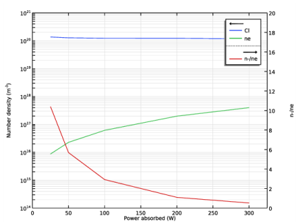
Locate the Data section. From the Dataset list, choose Corr power sweep/Parametric Solutions 1 (sol2).
4
From the Time selection list, choose Last.
5
Click to expand the Title section. From the Title type list, choose None.
6
Locate the Plot Settings section. Select the x-axis label check box.
7
8
Select the y-axis label check box.
9
In the associated text field, type Number density (m<sup>-3</sup>).
10
Select the Two y-axes check box.
11
Select the Secondary y-axis label check box.
12
13
Locate the Axis section. Select the Manual axis limits check box.
14
In the x minimum text field, type 0.
15
In the x maximum text field, type 325.
16
In the y minimum text field, type 1e14.
17
In the y maximum text field, type 1e21.
18
In the Secondary y minimum text field, type 0.
19
In the Secondary y maximum text field, type 20.
20
Select the y-axis log scale check box.
Global 1
1
Right-click Corr power sweep and choose Global.
2
In the Settings window for Global, locate the y-Axis Data section.
3
4
Locate the x-Axis Data section. From the Axis source data list, choose Pabs.
5
Click to expand the Legends section. From the Legends list, choose Manual.
6
Global 2
1
In the Model Builder window, right-click Corr power sweep and choose Global.
2
In the Settings window for Global, locate the y-Axis section.
3
Select the Plot on secondary y-axis check box.
4
Locate the y-Axis Data section. In the table, enter the following settings:
5
Locate the x-Axis Data section. From the Axis source data list, choose Pabs.
6
Locate the Legends section. From the Legends list, choose Manual.
7
8
In the Corr power sweep toolbar, click  Plot.
Create a second plot with the data from the Malyshev and Donnelly study that shows the electron density, and the atomic chlorine density as a function of the absorbed power.
Malyshev and Donnelly power sweep
1
In the Home toolbar, click  Add Plot Group and choose 1D Plot Group.
2
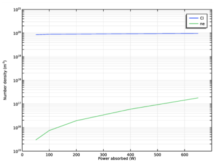
In the Settings window for 1D Plot Group, type Malyshev and Donnelly power sweep in the Label text field.
3
Locate the Data section. From the Dataset list, choose Malyshev and Donnelly power sweep/Parametric Solutions 2 (sol9).
4
From the Time selection list, choose Last.
5
Locate the Title section. From the Title type list, choose None.
6
Locate the Plot Settings section. Select the x-axis label check box.
7
8
Select the y-axis label check box.
9
In the associated text field, type Number density (m<sup>-3</sup>).
10
Locate the Axis section. Select the Manual axis limits check box.
11
In the x minimum text field, type 0.
12
In the x maximum text field, type 700.
13
In the y minimum text field, type 1e15.
14
In the y maximum text field, type 1e21.
15
Select the y-axis log scale check box.
Global 1
1
Right-click Malyshev and Donnelly power sweep and choose Global.
2
In the Settings window for Global, locate the y-Axis Data section.
3
4
Locate the x-Axis Data section. From the Axis source data list, choose Pabs.
5
Locate the Legends section. From the Legends list, choose Manual.
6
7
In the Malyshev and Donnelly power sweep toolbar, click  Plot.
Corr and Efremov pressure sweep
1
In the Home toolbar, click  Add Plot Group and choose 1D Plot Group.
Create a third plot with the data from the Corr and Efremov studies that shows the electron density, and the atomic chlorine density as a function of the pressure.
2
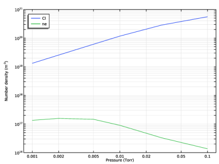
In the Settings window for 1D Plot Group, type Corr and Efremov pressure sweep in the Label text field.
3
Locate the Data section. From the Dataset list, choose None.
4
Locate the Title section. From the Title type list, choose None.
5
Locate the Plot Settings section. Select the x-axis label check box.
6
7
Select the y-axis label check box.
8
In the associated text field, type Number density (m<sup>-3</sup>).
9
Locate the Axis section. Select the Manual axis limits check box.
10
In the x minimum text field, type 8e-4.
11
In the x maximum text field, type 125e-3.
12
In the y minimum text field, type 1e16.
13
In the y maximum text field, type 1e21.
14
Select the x-axis log scale check box.
15
Select the y-axis log scale check box.
16
Locate the Legend section. From the Position list, choose Upper left.
Global 1
1
Right-click Corr and Efremov pressure sweep and choose Global.
2
In the Settings window for Global, locate the Data section.
3
From the Dataset list, choose Corr pressure sweep/Parametric Solutions 3 (sol16).
4
From the Time selection list, choose Last.
5
Locate the y-Axis Data section. In the table, enter the following settings:
6
Locate the x-Axis Data section. From the Axis source data list, choose p0.
7
From the Parameter list, choose Expression.
8
In the Expression text field, type p0.
9
From the Unit list, choose Torr.
10
Locate the Legends section. From the Legends list, choose Manual.
11
Global 2
1
In the Model Builder window, right-click Corr and Efremov pressure sweep and choose Global.
2
In the Settings window for Global, locate the Data section.
3
From the Dataset list, choose Efremov pressure sweep/Parametric Solutions 4 (sol24).
4
From the Time selection list, choose Last.
5
Locate the y-Axis Data section. In the table, enter the following settings:
6
Locate the x-Axis Data section. From the Axis source data list, choose p0.
7
From the Parameter list, choose Expression.
8
In the Expression text field, type p0.
9
From the Unit list, choose Torr.
10
Locate the Legends section. From the Legends list, choose Manual.
11
12
In the Corr and Efremov pressure sweep toolbar, click  Plot.
Efremov pressure sweep
1
In the Home toolbar, click  Add Plot Group and choose 1D Plot Group.
Create the fourth and last plot with the data from the Efremov study that shows the electron temperature as a function of the pressure.
2
In the Settings window for 1D Plot Group, type Efremov pressure sweep in the Label text field.
3
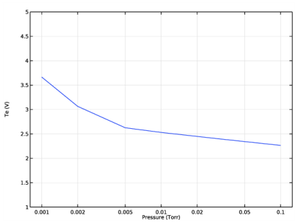
Locate the Data section. From the Dataset list, choose Efremov pressure sweep/Parametric Solutions 4 (sol24).
4
From the Time selection list, choose Last.
5
Locate the Title section. From the Title type list, choose None.
6
Locate the Plot Settings section. Select the x-axis label check box.
7
8
Select the y-axis label check box.
9
10
Locate the Axis section. Select the Manual axis limits check box.
11
In the x minimum text field, type 8e-4.
12
In the x maximum text field, type 125e-3.
13
In the y minimum text field, type 1.
14
In the y maximum text field, type 5.
15
Select the x-axis log scale check box.
16
Locate the Legend section. Clear the Show legends check box.
Global 1
1
Right-click Efremov pressure sweep and choose Global.
2
In the Settings window for Global, locate the y-Axis Data section.
3
4
Locate the x-Axis Data section. From the Axis source data list, choose p0.
5
From the Parameter list, choose Expression.
6
In the Expression text field, type p0.
7
From the Unit list, choose Torr.
8
In the Efremov pressure sweep toolbar, click  Plot.