|
|
|
|
•
|
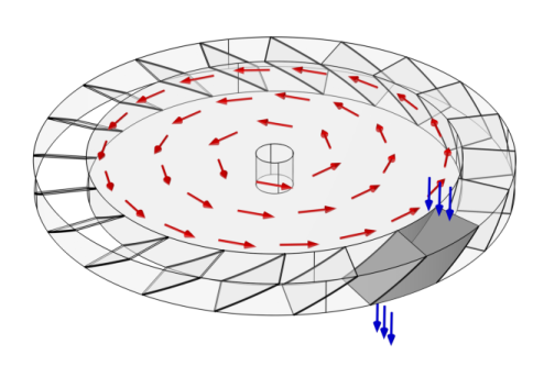
The particles experience diffuse scattering at the blade walls, following the distribution of velocity direction called Lambert’s cosine law or Knudsen’s cosine law.
|
|
•
|
|
•
|
T = 300 K is the ambient temperature,
|
|
•
|
|
•
|
|
•
|
Fcen is the centrifugal force,
|
|
•
|
Fcor is the Coriolis force,
|
|
•
|
Feul is the Euler force,
|
|
•
|
Ω (SI unit: rad/s) is the angular velocity of the rotating frame, and
|
|
•
|
r (SI unit: m) is the displacement from the center of rotation to the atom’s position.
|

|
1
|
|
2
|
|
3
|
Click Add.
|
|
4
|
Click
|
|
5
|
|
6
|
Click
|
|
1
|
|
2
|
Browse to the model’s Application Libraries folder and double-click the file turbomolecular_pump_geom_sequence.mph.
|
|
3
|
|
4
|
|
1
|
|
2
|
|
1
|
|
2
|
|
3
|
|
4
|
Browse to the model’s Application Libraries folder and double-click the file turbomolecular_pump_parameters.txt.
|
|
1
|
In the Model Builder window, under Component 1 (comp1) right-click Definitions and choose Variables.
|
|
2
|
|
1
|
|
2
|
In the Settings window for Mathematical Particle Tracing, locate the Particle Release and Propagation section.
|
|
3
|
|
1
|
In the Model Builder window, under Component 1 (comp1)>Mathematical Particle Tracing (pt) click Particle Properties 1.
|
|
2
|
|
3
|
|
1
|
|
2
|
|
3
|
|
1
|
|
2
|
|
3
|
|
4
|
|
5
|
|
6
|
|
7
|
|
8
|
Click to expand the Advanced Settings section. Select the Subtract moving frame velocity from initial particle velocity check box.
|
|
1
|
|
2
|
|
3
|
|
4
|
|
5
|
|
6
|
|
7
|
|
8
|
Locate the Advanced Settings section. Select the Subtract moving frame velocity from initial particle velocity check box.
|
|
1
|
|
2
|
In the Settings window for Particle Counter, type Particle Counter (Inlet 1 Transmission) in the Label text field.
|
|
3
|
|
4
|
|
1
|
|
2
|
In the Settings window for Particle Counter, type Particle Counter (Inlet 2 Transmission) in the Label text field.
|
|
3
|
|
4
|
|
1
|
|
2
|
In the Settings window for Thermal Re-Emission, type Root and Blade Surfaces in the Label text field.
|
|
3
|
|
4
|
|
1
|
|
2
|
|
3
|
|
4
|
|
5
|
Locate the Frame Settings section. Select the Subtract moving frame velocity from reflected particle velocity check box.
|
|
1
|
|
2
|
|
3
|
|
4
|
|
1
|
|
2
|
|
3
|
Click
|
|
1
|
|
2
|
|
3
|
|
4
|
|
5
|
|
1
|
|
1
|
In the Model Builder window, expand the Results>Particle Trajectories (pt)>Particle Trajectories 1 node, then click Color Expression 1.
|
|
2
|
In the Settings window for Color Expression, click Replace Expression in the upper-right corner of the Expression section. From the menu, choose Component 1 (comp1)>Mathematical Particle Tracing>Particle statistics>pt.prf - Particle release feature.
|
|
3
|
|
1
|
|
2
|
|
3
|
|
4
|
|
5
|
|
1
|
|
2
|
|
3
|
|
4
|
|
5
|
|
1
|
|
2
|
|
4
|
|
5
|
|
6
|
|
7
|
|
1
|
|
2
|
|
1
|
|
2
|
|
1
|
|
2
|
|
1
|
|
2
|
|
4
|
|
5
|
|
1
|
|
2
|
|
1
|
|
2
|
|
4
|
|
5
|
|
1
|
|
2
|
|
3
|
|
4
|
Browse to the model’s Application Libraries folder and double-click the file turbomolecular_pump_geom_sequence_parameters.txt.
|
|
1
|
|
2
|
|
3
|
|
4
|
|
5
|
|
6
|
|
1
|
|
2
|
|
3
|
|
1
|
|
2
|
Select the object cyl1 only.
|
|
3
|
|
4
|
|
5
|
Select the object cyl2 only.
|
|
6
|
|
1
|
|
2
|
|
3
|
|
4
|
|
5
|
|
6
|
|
7
|
|
8
|
|
9
|
|
10
|
|
11
|
|
12
|
|
1
|
|
2
|
|
3
|
|
4
|
|
5
|
|
6
|
|
7
|
|
8
|
|
9
|
|
10
|
|
11
|
|
12
|
|
1
|
|
2
|
Select the object dif1 only.
|
|
3
|
|
4
|
|
5
|
|
1
|
|
2
|
Select the object par1 only.
|
|
3
|
|
4
|
|
1
|
|
2
|
On the object par2, select Boundary 7 only.
|
|
3
|
|
4
|
|
5
|
On the object par2, select Domains 1–3 only.
|
|
6
|
|
7
|
|
1
|
|
2
|
|
3
|
|
4
|
On the object del1, select Boundary 3 only.
|
|
1
|
|
2
|
|
3
|
|
4
|
On the object del1, select Boundary 4 only.
|
|
1
|
|
2
|
|
3
|
|
4
|
On the object del1, select Boundary 1 only.
|
|
1
|
|
2
|
|
3
|
|
4
|
On the object del1, select Boundary 6 only.
|
|
1
|
|
2
|
|
3
|
|
4
|
On the object del1, select Boundaries 2 and 5 only.
|
|
1
|
|
2
|
|
3
|
|
4
|
|
5
|
|
6
|
Click OK.
|