PDF

Virtual Operations on a Wheel Rim Geometry
Introduction
CAD geometries, especially those imported from CAD design software, may contain small features, such as faces or edges, that could significantly increase the number of mesh elements in the model. An efficient modeling approach is to avoid such small features by using virtual geometry operations to “hide” them from the mesher. A benefit of using virtual geometry operations is also that the curvature of the geometry is preserved, which could be important for certain physics applications, such as stress analysis.
In this tutorial you prepare a wheel rim geometry for stress analysis by defeaturing it using virtual geometry operations. The stress analysis is described in the model Submodel of a Wheel Rim found in the Application Libraries for the Structural Mechanics Module.
Model Definition
The geometry to be meshed is of a ten-spoke rim design, shown in Figure 1.
Figure 1: Wheel rim geometry.
To provide accurate results for the stiffness of the rim create a mesh for the analysis using the default normal predefined mesh settings. Apply virtual geometry operations to reduce the number of elements in the mesh.
Results and Discussion
The mesh generated with the original geometry consists of about 260,000 tetrahedral elements, see Figure 2 below.
Figure 2: Mesh of the geometry before applying virtual geometry operations
Due to small faces and edges, the mesh generated with a default normal size setting contains warning messages. These messages indicate that some small features could not be resolved by the mesher using the current settings. The warnings can help in locating these geometric entities.
The final mesh, after the virtual geometry operations, consists of about 180,000 tetrahedral elements, see Figure 3 below, which means a reduction of about 30% using the same mesh settings.
Figure 3: Mesh of the geometry after applying virtual geometry operations
This is a significant reduction of elements which reduces the memory requirements for computing the solution.
Note: The number of elements vary based on the used geometry kernel. If you are using the CAD kernel you can expect fewer elements than the value given in this document.
Notes About the COMSOL Implementation
Virtual geometry operations appear after the Finalize node in the geometry sequence. Virtual geometry operations do not modify the geometry, rather they hide geometric entities, such as faces, edges or vertices, from the mesher. As a result a virtual geometry is meshed, hence the name of these operations.
As a starting point for where on the geometry to apply virtual operations use the information from the warning messages provided by the mesher. Warnings are generated for those small faces or edges that the mesher cannot resolve with the current settings.
For an efficient workflow you can take advantage of the symmetry of the rim design. Rather than creating selections on the full wheel geometry you can apply the virtual operations on only a fifth of the rim. When done recreate the full rim geometry from the segments. The selections of the virtual operations automatically extends to include the full geometry.
Application Library path: COMSOL_Multiphysics/Meshing_Tutorials/wheel_rim
Modeling Instructions
From the File menu, choose New.
New
In the New window, click  Model Wizard.
Model Wizard
1
In the Model Wizard window, click  3D.
2
Geometry 1
Import 1 (imp1)
The wheel rim geometry has been saved in the COMSOL MPHBIN-format.
1
In the Home toolbar, click  Import.
2
In the Settings window for Import, locate the Import section.
3
Click Browse.
4
5
Click Import.
Now, generate the full geometry using a transform operation.
Rotate 1 (rot1)
1
In the Geometry toolbar, click  Transforms and choose Rotate.
2
3
In the Settings window for Rotate, locate the Rotation section.
4
Click  Range.
5
In the Range dialog box, choose Number of values from the Entry method list.
6
In the Start text field, type 0.
7
In the Stop text field, type 4/5*360.
8
In the Number of values text field, type 5.
9
Click Replace.
10
Right-click Rotate 1 (rot1) and choose Build Selected.
11
Click the  Zoom Extents button in the Graphics toolbar.
Form Union (fin)
Continue with adjusting the repair tolerance for the Form Union operation. This is sometimes necessary when working with imported CAD design geometries.
1
In the Model Builder window, click Form Union (fin).
2
In the Settings window for Form Union/Assembly, locate the Form Union/Assembly section.
3
From the Repair tolerance list, choose Relative.
4
In the Relative repair tolerance text field, type 2e-5.
5
In the Geometry toolbar, click  Build All.
Mesh 1
1
In the Model Builder window, under Component 1 (comp1) click Mesh 1.
2
In the Settings window for Mesh, locate the Physics-Controlled Mesh section.
3
From the Element size list, choose Fine.
4
Click  Build All.
Warning 1
In the figure below you can see the regions of high mesh density around the bolt holes and in the region of the fillets between the spoke and the rim drum.
These regions indicate small faces or short edges, which you can also locate if you examine the entities reported in the warning nodes for the mesh.
Geometry 1
Using the Form Composite Faces operation you will merge the faces of several fillets in the geometry.
First, disable the Rotate 1 node to work only with the reduced geometry, which will limit the number of selections you have to create for the virtual operations.
Rotate 1 (rot1)
In the Model Builder window, under Component 1 (comp1)>Geometry 1 right-click Rotate 1 (rot1) and choose Disable.
Form Composite Faces 1 (cmf1)
1
In the Geometry toolbar, click  Virtual Operations and choose Form Composite Faces.
To add faces to the selection, you can pick faces one by one in the Graphics window, or use the Select Box tool from the Graphics toolbar to select multiple faces at once. A faster alternative is to enter, or copy and paste the list of face numbers from the instructions into the Paste Selection dialog box.
2
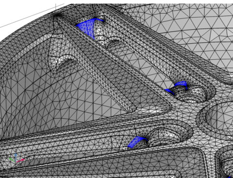
Go to the Form Composite Faces window, under the Input section click the Paste Selection button. In the list enter: 2-9,11-17,19-27, 29, 31-46, 51-110, 112-136, 138-160, 162-197, 199-208.
3
In the Settings window for Form Composite Faces, click  Build Selected.
Rotate 1 (rot1)
Before meshing you can generate the full geometry of the wheel rim, by enabling the Rotate 1 node in the geometry sequence.
1
Right-click Rotate 1 (rot1) and choose Enable.
2
In the Geometry toolbar, click  Build All.
Form Composite Domains 1 (cmd1)
The geometry now contains interior boundaries, which delimit five distinct domains. As the entire rim is made of the same material, you can create a single domain by the Form Composite Domains operation.
1
In the Geometry toolbar, click  Virtual Operations and choose Form Composite Domains.
2
Click the  Select All button in the Graphics toolbar.
3
In the Settings window for Form Composite Domains, click  Build Selected.
Mesh 1
Finally mesh the geometry of the rim.
1
In the Model Builder window, under Component 1 (comp1) right-click Mesh 1 and choose Build All.