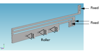
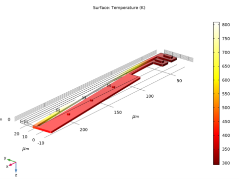
PDF

Thermal Microactuator Simplified
Introduction
This example model consists of a two-hot-arm thermal actuator made of polysilicon. The actuator is activated through thermal expansion. The temperature increase required to deform the two hot arms, and thus displace the actuator, is obtained through Joule heating (resistive heating). The greater expansion of the hot arms, compared to the cold arm, causes a bending of the actuator.
The material properties of polysilicon are temperature dependent, which means that the involved physics phenomena are fully coupled. The electric current through the hot arms increases the temperature in the actuator, which in turn causes thermal expansion and changes the electrical conductivity of the material.
The actuator’s operation thus involves three coupled physics phenomena: electric current conduction, heat conduction with heat generation, and structural stresses and strains due to thermal expansion.
In this example the thermal expansion is included manually using the Equation View. Furthermore, only linear strains are considered, which is a valid approximation provided deformations are small. Using the Structural Mechanics Module or the MEMS Module, you can directly include the thermal equation in the physics and also take into account possible large deformations; see the model Thermal Microactuator in the Structural Mechanics Module or MEMS Module Application Libraries.
Model Definition
Figure 1 shows the actuator’s parts and dimensions as well as its position on top of a substrate surface.
Figure 1: The thermal microactuator.
Boundary Conditions and Constraints
An electric potential is applied between the bases of the hot arms’ anchors. The cold arm anchor and all other surfaces are electrically insulated.
Figure 2: Electrical boundary conditions.
The temperature of the base of the three anchors and the three dimples is fixed to that of the substrate’s constant temperature. Because the structure is sandwiched, all other boundaries interact thermally with the surroundings by conduction through thin layers of air.
The heat transfer coefficient is given by the thermal conductivity of air divided by the distance to the surrounding surfaces for the system. This exercise uses different heat transfer coefficients for the actuator’s upper and other surfaces.
Figure 3: Heat-transfer boundary conditions.
All three arms are mechanically fixed at the base of the three anchors. The dimples can move freely in the plane of the substrate (the xy-plane in the figure) but do not move in the direction perpendicular to the substrate (the z direction).
Figure 4: Structural boundary conditions and constraints.
Geometry Programming Operations
The model geometry uses a conditional If + EndIf statement to implement two distinct designs: a two-arms or a three-arms actuator design. It is possible to switch from one design to the other by means of a parameter.
Results
Figure 5 shows the surface temperature distribution for the actuator design with two arms. It also illustrates the displacement field through a deformation plot.
Figure 5: Temperature (surface) and displacement (deformation) in the two-arms actuator design.
For the two-arms design, the computed displacement at the tip of the actuator is about 3.3 μm.
Figure 6 shows the surface temperature distribution for the actuator design with 3 arms only.
Figure 6: Temperature (surface) and displacement (deformation) in the three arms actuator design.
For the two-arms design, the computed displacement at the tip of the actuator is about 1.1 μm.
Notes About the COMSOL Implementation
Using Equation View, you can access the equation level. There you can modify the strain definition used by the linear elastic material model.
The thermal strain to be added is:
Here α is the material thermal expansion coefficient, T the current temperature, and T0 the strain reference temperature.
To enable the equation view, click the Show button () and choose Equation View. You can then access the equation view by expanding each node of the model tree.
Application Library path: COMSOL_Multiphysics/Multiphysics/thermal_actuator_simplified
Modeling Instructions
From the File menu, choose New.
New
In the New window, click  Model Wizard.
Model Wizard
1
In the Model Wizard window, click  3D.
2
In the Select Physics tree, select Heat Transfer>Electromagnetic Heating>Joule Heating.
3
Click Add.
4
In the Select Physics tree, select Structural Mechanics>Solid Mechanics (solid).
5
Click Add.
6
Click  Study.
7
In the Select Study tree, select General Studies>Stationary.
8
Thermal Actuator
1
In the Model Builder window, right-click Component 1 (comp1) and choose Rename.
2
In the Rename Component dialog box, type Thermal Actuator in the New label text field.
3
Global Definitions
Parameters 1
1
In the Model Builder window, under Global Definitions click Parameters 1.
2
In the Settings window for Parameters, locate the Parameters section.
3
Geometry 1
1
In the Model Builder window, under Thermal Actuator (comp1) click Geometry 1.
2
In the Settings window for Geometry, locate the Units section.
3
From the Length unit list, choose µm.
If 1 (if1)
1
In the Geometry toolbar, click  Programming and choose If + End If.
2
In the Settings window for If, locate the If section.
3
In the Condition text field, type (noa==3).
Work Plane 1 (wp1)
1
In the Geometry toolbar, click  Work Plane.
2
In the Settings window for Work Plane, click  Show Work Plane.
Work Plane 1 (wp1)>Plane Geometry
In the Model Builder window, click Plane Geometry.
Work Plane 1 (wp1)>Rectangle 1 (r1)
1
In the Work Plane toolbar, click  Rectangle.
2
In the Settings window for Rectangle, locate the Size and Shape section.
3
In the Width text field, type L3.
4
In the Height text field, type dw.
5
Locate the Position section. In the xw text field, type L-L3. Leave yw at the default value 0.
Rectangles 2-9
Proceed to create eight additional rectangles with the following settings:
Work Plane 1 (wp1)>Union 1 (uni1)
1
In the Work Plane toolbar, click  Booleans and Partitions and choose Union.
2
Click in the Graphics window and then press Ctrl+A to select all objects.
3
In the Settings window for Union, locate the Union section.
4
Clear the Keep interior boundaries check box.
Work Plane 1 (wp1)>Fillet 1 (fil1)
1
In the Work Plane toolbar, click  Fillet.
2
On the object uni1, select Points 1, 2, 4–9, 11–14, 16, 17, 19–23, and 28 only.
It might be easier to select the points by using the Selection List window. To open this window, in the Home toolbar click Windows and choose Selection List. (If you are running the cross-platform desktop, you find Windows in the main menu.)
3
In the Settings window for Fillet, locate the Radius section.
4
In the Radius text field, type d/3.
Extrude 1 (ext1)
1
In the Model Builder window, right-click Geometry 1 and choose Extrude.
2
In the Settings window for Extrude, locate the Distances section.
3
Work Plane 2 (wp2)
1
In the Geometry toolbar, click  Work Plane.
2
In the Settings window for Work Plane, click  Show Work Plane.
Work Plane 2 (wp2)>Plane Geometry
In the Model Builder window, click Plane Geometry.
Work Plane 2 (wp2)>Rectangle 1 (r1)
1
In the Work Plane toolbar, click  Rectangle.
2
In the Settings window for Rectangle, locate the Size and Shape section.
3
In the Width text field, type wb-2*d.
4
In the Height text field, type 2.5*(wb-2*d).
5
Locate the Position section. In the xw text field, type d.
6
In the yw text field, type (dw+d+2*gap)+(dw+gap+d)-2.5*(wb-2*d)-d.
Work Plane 2 (wp2)>Rectangle 2 (r2)
1
In the Work Plane toolbar, click  Rectangle.
2
In the Settings window for Rectangle, locate the Size and Shape section.
3
In the Width text field, type wb-2*d.
4
In the Height text field, type 2.5*(wb-2*d).
5
Locate the Position section. In the xw text field, type L-L2-wb+d.
6
In the yw text field, type d.
Work Plane 2 (wp2)>Rectangle 3 (r3)
1
In the Work Plane toolbar, click  Rectangle.
2
In the Settings window for Rectangle, locate the Size and Shape section.
3
In the Width text field, type wb-2*d.
4
In the Height text field, type 2.5*(wb-2*d).
5
Locate the Position section. In the xw text field, type L-L3-L4-wb+d.
6
In the yw text field, type d.
Work Plane 2 (wp2)>Fillet 1 (fil1)
1
In the Work Plane toolbar, click  Fillet.
2
Click the  Zoom Extents button in the Graphics toolbar.
3
On each of the rectangles r1, r2, and r3, in turn, select all four corner points.
4
In the Settings window for Fillet, locate the Radius section.
5
In the Radius text field, type d/3.
Work Plane 2 (wp2)>Circle 1 (c1)
1
In the Work Plane toolbar, click  Circle.
2
In the Settings window for Circle, locate the Size and Shape section.
3
In the Radius text field, type d/2.
4
Locate the Position section. In the xw text field, type L-L3/4.
5
In the yw text field, type dw/2.
Work Plane 2 (wp2)>Circle 2 (c2)
1
In the Work Plane toolbar, click  Circle.
2
In the Settings window for Circle, locate the Size and Shape section.
3
In the Radius text field, type d/2.
4
Locate the Position section. In the xw text field, type L-L3/2.
5
In the yw text field, type dw/2.
Work Plane 2 (wp2)>Circle 3 (c3)
1
In the Work Plane toolbar, click  Circle.
2
In the Settings window for Circle, locate the Size and Shape section.
3
In the Radius text field, type d/2.
4
Locate the Position section. In the xw text field, type L-3*L3/4.
5
In the yw text field, type dw/2.
Extrude 2 (ext2)
1
In the Model Builder window, right-click Geometry 1 and choose Extrude.
2
In the Settings window for Extrude, locate the Distances section.
3
4
Select the Reverse direction check box.
Union 1 (uni1)
1
In the Geometry toolbar, click  Booleans and Partitions and choose Union.
2
Click in the Graphics window and then press Ctrl+A to select both objects.
3
In the Settings window for Union, locate the Union section.
4
Clear the Keep interior boundaries check box.
5
Click  Build Selected.
Explicit Selection 1 (sel1)
1
In the Geometry toolbar, click  Selections and choose Explicit Selection.
2
In the Settings window for Explicit Selection, locate the Entities to Select section.
3
From the Geometric entity level list, choose Boundary.
4
On the object uni1, select Boundary 10 only.
5
Locate the Resulting Selection section. Clear the Keep selection check box.
6
Find the Cumulative selection subsection. Click New.
7
In the New Cumulative Selection dialog box, type Ground in the Name text field.
8
Explicit Selection 2 (sel2)
1
In the Geometry toolbar, click  Selections and choose Explicit Selection.
2
In the Settings window for Explicit Selection, locate the Entities to Select section.
3
From the Geometric entity level list, choose Boundary.
4
On the object uni1, select Boundary 29 only.
5
Locate the Resulting Selection section. Clear the Keep selection check box.
6
Find the Cumulative selection subsection. Click New.
7
In the New Cumulative Selection dialog box, type Applied Voltage in the Name text field.
8
Explicit Selection 3 (sel3)
1
In the Geometry toolbar, click  Selections and choose Explicit Selection.
2
In the Settings window for Explicit Selection, locate the Entities to Select section.
3
From the Geometric entity level list, choose Boundary.
4
On the object uni1, select Boundary 48 only.
5
Locate the Resulting Selection section. Clear the Keep selection check box.
6
Find the Cumulative selection subsection. Click New.
7
In the New Cumulative Selection dialog box, type Third in the Name text field.
8
Explicit Selection 4 (sel4)
1
In the Geometry toolbar, click  Selections and choose Explicit Selection.
2
In the Settings window for Explicit Selection, locate the Entities to Select section.
3
From the Geometric entity level list, choose Boundary.
4
On the object uni1, select Boundary 4 only.
5
Locate the Resulting Selection section. Clear the Keep selection check box.
6
Find the Cumulative selection subsection. Click New.
7
In the New Cumulative Selection dialog box, type Upper Surface in the Name text field.
8
Explicit Selection 5 (sel5)
1
In the Geometry toolbar, click  Selections and choose Explicit Selection.
2
In the Settings window for Explicit Selection, locate the Entities to Select section.
3
From the Geometric entity level list, choose Boundary.
4
On the object uni1, select Boundaries 1–3, 5–9, 11–28, 30–47, and 49–92 only.
5
In the Model Builder window, click Explicit Selection 5 (sel5).
6
Locate the Resulting Selection section. Clear the Keep selection check box.
7
Find the Cumulative selection subsection. Click New.
8
In the New Cumulative Selection dialog box, type Other Surface in the Name text field.
9
Explicit Selection 6 (sel6)
1
In the Geometry toolbar, click  Selections and choose Explicit Selection.
2
In the Settings window for Explicit Selection, locate the Entities to Select section.
3
From the Geometric entity level list, choose Point.
4
On the object uni1, select Point 154 only.
5
Locate the Resulting Selection section. Clear the Keep selection check box.
6
Find the Cumulative selection subsection. Click New.
7
In the New Cumulative Selection dialog box, type Tip in the Name text field.
8
Explicit Selection 7 (sel7)
1
In the Geometry toolbar, click  Selections and choose Explicit Selection.
2
In the Settings window for Explicit Selection, locate the Entities to Select section.
3
From the Geometric entity level list, choose Boundary.
4
On the object uni1, select Boundaries 67, 72, and 77 only.
5
Locate the Resulting Selection section. Clear the Keep selection check box.
6
Find the Cumulative selection subsection. Click New.
7
In the New Cumulative Selection dialog box, type Dimples in the Name text field.
8
End If 1 (endif1)
1
In the Model Builder window, click End If 1 (endif1).
2
In the Settings window for End If, click  Build Selected.
Global Definitions
Parameters 1
1
In the Model Builder window, under Global Definitions click Parameters 1.
2
In the Settings window for Parameters, locate the Parameters section.
3
Geometry 1
If 2 (if2)
1
In the Geometry toolbar, click  Programming and choose If + End If.
2
In the Settings window for If, locate the If section.
3
In the Condition text field, type (noa==2).
Work Plane 3 (wp3)
1
In the Model Builder window, under Thermal Actuator (comp1)>Geometry 1 right-click Work Plane 1 (wp1) and choose Duplicate.
2
Expand the Work Plane 3 (wp3) node.
Plane Geometry
In the Model Builder window, expand the Thermal Actuator (comp1)>Geometry 1>Work Plane 3 (wp3)>Plane Geometry node.
Work Plane 3 (wp3)>Rectangle 6 (r6), Work Plane 3 (wp3)>Rectangle 7 (r7), Work Plane 3 (wp3)>Rectangle 8 (r8)
1
In the Model Builder window, under Thermal Actuator (comp1)>Geometry 1>Work Plane 3 (wp3)>Plane Geometry, Ctrl-click to select Rectangle 6 (r6), Rectangle 7 (r7), and Rectangle 8 (r8).
2
Extrude 3 (ext3)
1
In the Model Builder window, under Thermal Actuator (comp1)>Geometry 1 right-click Extrude 1 (ext1) and choose Duplicate.
2
In the Settings window for Extrude, locate the General section.
3
From the Work plane list, choose Work Plane 3 (wp3).
4
Find the Input objects subsection. Select the  Activate Selection toggle button.
5
6
Click  Build Selected.
Work Plane 4 (wp4)
1
In the Model Builder window, under Thermal Actuator (comp1)>Geometry 1 right-click Work Plane 2 (wp2) and choose Duplicate.
2
Expand the Work Plane 4 (wp4) node.
Work Plane 4 (wp4)>Rectangle 1 (r1)
1
In the Model Builder window, expand the Thermal Actuator (comp1)>Geometry 1>Work Plane 4 (wp4)>Plane Geometry node, then click Rectangle 1 (r1).
2
Right-click Rectangle 1 (r1) and choose Disable.
Extrude 4 (ext4)
1
In the Model Builder window, under Thermal Actuator (comp1)>Geometry 1 right-click Extrude 2 (ext2) and choose Duplicate.
2
In the Settings window for Extrude, locate the General section.
3
From the Work plane list, choose Work Plane 4 (wp4).
4
Find the Input objects subsection. Select the  Activate Selection toggle button.
5
6
Click  Build Selected.
Union 2 (uni2)
1
In the Model Builder window, under Thermal Actuator (comp1)>Geometry 1 right-click Union 1 (uni1) and choose Duplicate.
2
Click in the Graphics window and then press Ctrl+A to select both objects.
Explicit Selection 8 (sel8)
1
In the Model Builder window, under Thermal Actuator (comp1)>Geometry 1 right-click Explicit Selection 1 (sel1) and choose Duplicate.
2
In the Settings window for Explicit Selection, locate the Entities to Select section.
3
Find the Entities to select subsection. Select the  Activate Selection toggle button.
4
On the object uni2, select Boundary 28 only.
5
Click  Build Selected.
Explicit Selection 9 (sel9)
1
In the Model Builder window, under Thermal Actuator (comp1)>Geometry 1 right-click Explicit Selection 2 (sel2) and choose Duplicate.
2
On the object uni2, select Boundary 10 only.
3
In the Settings window for Explicit Selection, click  Build Selected.
Explicit Selection 10 (sel10)
1
In the Model Builder window, under Thermal Actuator (comp1)>Geometry 1 right-click Explicit Selection 4 (sel4) and choose Duplicate.
2
On the object uni2, select Boundary 4 only.
3
In the Settings window for Explicit Selection, click  Build Selected.
Explicit Selection 11 (sel11)
1
In the Model Builder window, under Thermal Actuator (comp1)>Geometry 1 right-click Explicit Selection 5 (sel5) and choose Duplicate.
2
On the object uni2, select Boundaries 1–3, 5–9, 11–27, and 29–66 only.
3
In the Settings window for Explicit Selection, click  Build Selected.
Explicit Selection 12 (sel12)
1
In the Model Builder window, under Thermal Actuator (comp1)>Geometry 1 right-click Explicit Selection 6 (sel6) and choose Duplicate.
2
On the object uni2, select Point 108 only.
3
In the Settings window for Explicit Selection, click  Build Selected.
Explicit Selection 13 (sel13)
1
In the Model Builder window, under Thermal Actuator (comp1)>Geometry 1 right-click Explicit Selection 7 (sel7) and choose Duplicate.
2
On the object uni2, select Boundaries 47, 52, and 57 only.
3
In the Settings window for Explicit Selection, click  Build Selected.
Form Union (fin)
1
In the Model Builder window, click Form Union (fin).
2
In the Settings window for Form Union/Assembly, click  Build Selected.
Definitions
Surface Contact
1
In the Definitions toolbar, click  Union.
2
In the Settings window for Union, locate the Geometric Entity Level section.
3
From the Level list, choose Boundary.
4
Locate the Input Entities section. Under Selections to add, click  Add.
5
In the Add dialog box, in the Selections to add list, choose Ground, Applied Voltage, and Third.
6
7
Right-click Union 1 and choose Rename.
8
In the Rename Union dialog box, type Surface Contact in the New label text field.
9
Add Material
1
In the Home toolbar, click  Add Material to open the Add Material window.
2
Go to the Add Material window.
3
In the tree, select Built-in>Polysilicon.
4
Click Add to Component in the window toolbar.
5
In the Home toolbar, click  Add Material to close the Add Material window.
Electric Currents (ec)
Electric Potential 1
1
In the Model Builder window, under Thermal Actuator (comp1) right-click Electric Currents (ec) and choose Electric Potential.
2
In the Settings window for Electric Potential, locate the Boundary Selection section.
3
From the Selection list, choose Applied Voltage.
4
Locate the Electric Potential section. In the V0 text field, type DV.
Ground 1
1
In the Physics toolbar, click  Boundaries and choose Ground.
2
In the Settings window for Ground, locate the Boundary Selection section.
3
From the Selection list, choose Ground.
Heat Transfer in Solids (ht)
In the Model Builder window, under Thermal Actuator (comp1) click Heat Transfer in Solids (ht).
Heat Flux 1
1
In the Physics toolbar, click  Boundaries and choose Heat Flux.
2
In the Settings window for Heat Flux, locate the Boundary Selection section.
3
From the Selection list, choose Other Surface.
A convective heat flux is used to model the heat flux through a thin air layer. The heat transfer coefficient, htc_s is defined as the ratio of the air thermal conductivity to the gap thickness.
4
Locate the Heat Flux section. Click the Convective heat flux button.
5
In the h text field, type htc_s.
Heat Flux 2
1
In the Physics toolbar, click  Boundaries and choose Heat Flux.
2
In the Settings window for Heat Flux, locate the Boundary Selection section.
3
From the Selection list, choose Upper Surface.
A convective heat flux is used to model the heat flux through a thin air layer. The heat transfer coefficient, htc_us is defined as the ratio of the air thermal conductivity to the gap thickness.
4
Locate the Heat Flux section. Click the Convective heat flux button.
5
In the h text field, type htc_us.
Temperature 1
1
In the Physics toolbar, click  Boundaries and choose Temperature.
2
In the Settings window for Temperature, locate the Boundary Selection section.
3
From the Selection list, choose Surface Contact.
Solid Mechanics (solid)
In the Model Builder window, under Thermal Actuator (comp1) click Solid Mechanics (solid).
Fixed Constraint 1
1
In the Physics toolbar, click  Boundaries and choose Fixed Constraint.
2
In the Settings window for Fixed Constraint, locate the Boundary Selection section.
3
From the Selection list, choose Surface Contact.
Roller 1
1
In the Physics toolbar, click  Boundaries and choose Roller.
2
In the Settings window for Roller, locate the Boundary Selection section.
3
From the Selection list, choose Dimples.
4
Click the  Show More Options button in the Model Builder toolbar.
5
In the Show More Options dialog box, in the tree, select the check box for the node Physics>Equation View.
6
Linear Elastic Material 1
1
Click the Refresh Equations button.
2
In the Model Builder window, expand the Thermal Actuator (comp1)>Solid Mechanics (solid)>Linear Elastic Material 1 node, then click Equation View.
3
In the Settings window for Equation View, locate the Variables section.
4
Study 1
In the Home toolbar, click  Compute.
Results
Point Evaluation 1
1
In the Results toolbar, click  Point Evaluation.
2
In the Settings window for Point Evaluation, locate the Selection section.
3
From the Selection list, choose Tip.
4
Locate the Expressions section. In the table, enter the following settings:
5
Click  Evaluate.
Volume Maximum 1
1
In the Results toolbar, click  More Derived Values and choose Maximum>Volume Maximum.
2
In the Settings window for Volume Maximum, locate the Selection section.
3
From the Selection list, choose All domains.
4
Locate the Expressions section. In the table, enter the following settings:
5
Click  Evaluate.
Deformation 1
1
In the Model Builder window, expand the Temperature (ht) node.
2
Right-click Surface and choose Deformation.
3
In the Settings window for Deformation, locate the Scale section.
4
Select the Scale factor check box.
5
6
In the Temperature (ht) toolbar, click  Plot.
Global Definitions
Parameters 1
Continue by computing the solution for the three arms actuator geometry case.
1
In the Model Builder window, under Global Definitions click Parameters 1.
2
In the Settings window for Parameters, locate the Parameters section.
3
Study 1
In the Home toolbar, click  Compute.
Results
Point Evaluation 1
1
In the Model Builder window, under Results>Derived Values click Point Evaluation 1.
2
In the Settings window for Point Evaluation, click  Evaluate.
Volume Maximum 1
1
In the Model Builder window, click Volume Maximum 1.
2
In the Settings window for Volume Maximum, click  Evaluate.