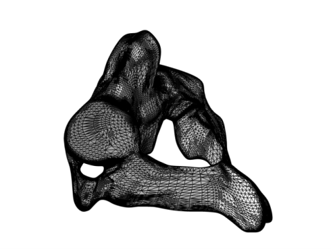
|
|
|
|
•
|
Using a Swept mesh operation to create a structured mesh.
|
|
1
|
|
2
|
Click
|
|
1
|
|
2
|
|
3
|
|
1
|
|
2
|
|
3
|
Click Browse.
|
|
4
|
|
5
|
|
6
|
|
1
|
|
2
|
|
1
|
|
2
|
|
3
|
|
4
|
|
5
|
|
6
|
|
7
|
|
8
|
Click the
 |
|
9
|
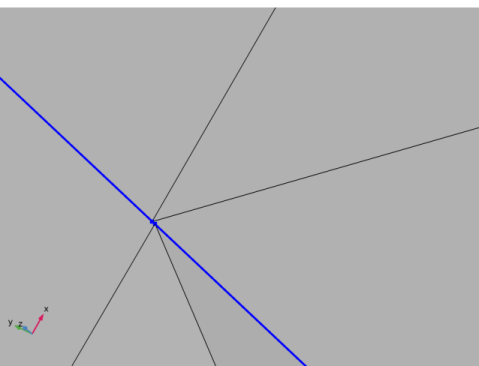
Open up the Selection List from the Windows menu on the Home toolbar. If there are more than 3 edges listed in the Selection List, go back to the Import 1 node and make sure that the setting Boundary partitioning is set to Minimal, then reimport the mesh. Keep the Selection List open as you will use it later on.
|
|
11
|
|
12
|
Click the
 |
|
1
|
|
2
|
|
3
|
|
4
|
|
5
|
|
6
|
Go to the Selection List.
|
|
8
|
|
1
|
|
2
|
Go to the Model Builder window.
|
|
3
|
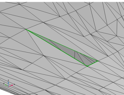
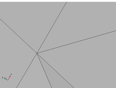
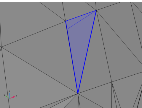
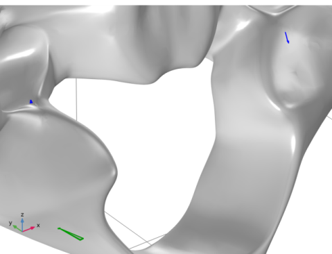
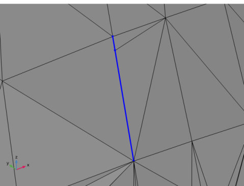
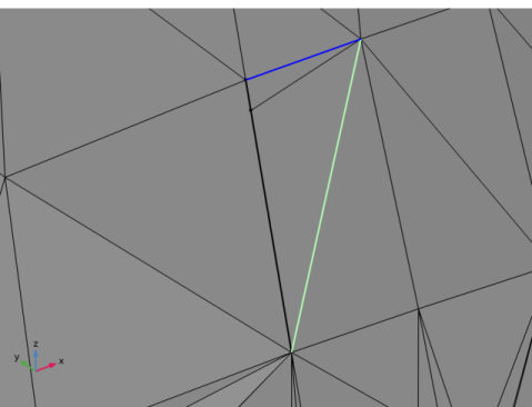
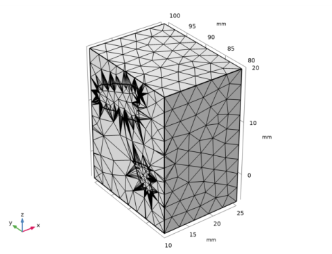
In the Graphics window, select element edges as in the image below (highlighted in blue and green) by clicking on the mesh edges with the mouse cursor.
 |
|
4
|
|
1
|
|
3
|
|
1
|
|
3
|
|
4
|
Click the
 |
|
5
|
|
7
|
|
8
|
|
9
|
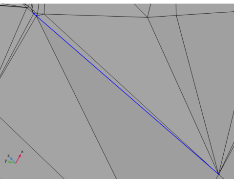
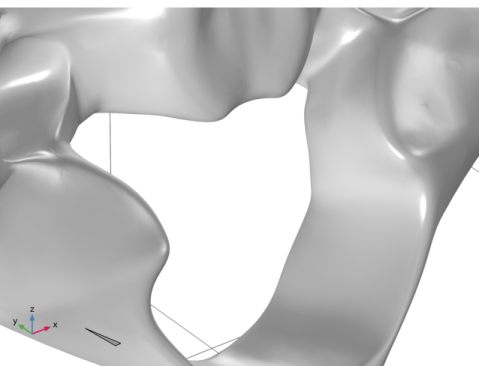
In the Maximum hole perimeter text field, type 2.3[mm]. The value you enter here should be slightly larger than the measured hole perimeter.
|
|
10
|
|
1
|
|
2
|
|
1
|
|
2
|
|
3
|
|
4
|
|
5
|
|
6
|
|
7
|
|
8
|
|
9
|
|
10
|
|
1
|
|
1
|
|
1
|
In the Mesh toolbar, click
|
|
2
|
|
3
|
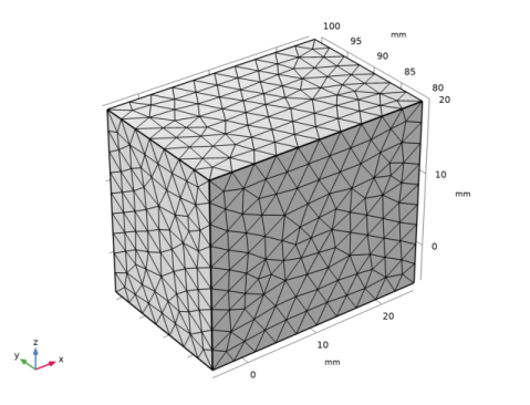
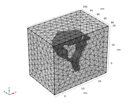
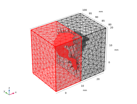
From the Source list, choose Meshing sequence. This will automatically suggest to import Mesh 2, which is the mesh of the block.
|
|
4
|
Click Import.
|
|
5
|
|
6
|
|
7
|
|
8
|
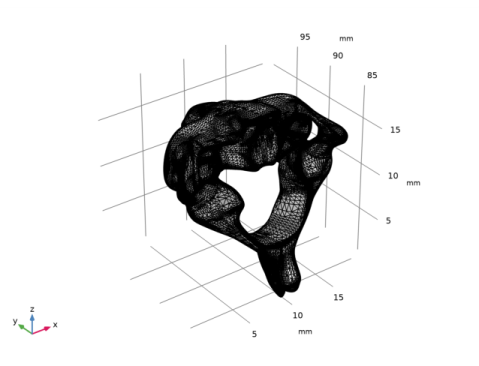
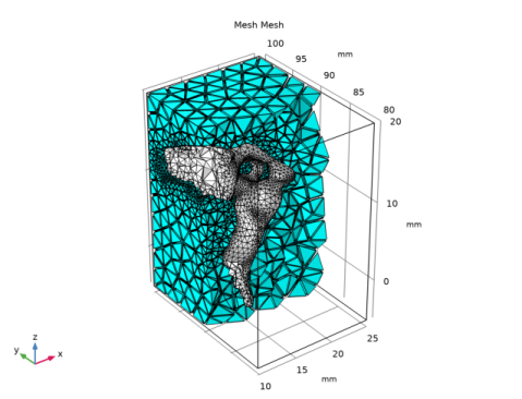
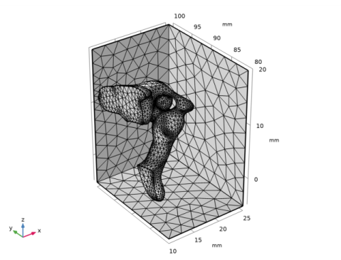
Rotate the mesh in the Graphics window to check that the vertebra is fully contained in the block, the two meshes should not intersect.
|
|
9
|
|
10
|
|
1
|
|
2
|
|
3
|
|
4
|
|
5
|
|
6
|
|
1
|
|
2
|
In the Selection List window, choose 1 (meshed), 2 (meshed), 3 (meshed), 4 (meshed), 5 (meshed), and 6 (meshed) by pressing down the Ctrl key at the same time as clicking them in the list.
 |
|
3
|
|
1
|
|
2
|
In the Settings window for Delete Entities, click
|
|
3
|
In the Selection list, confirm that we have the expected nine boundaries; six for the block and three for the vertebra. If there are more than 9 boundaries in the list, check the tolerance setting for the Intersect with plane operation.
|
|
4
|
Click the
 |
|
1
|
|
3
|
|
4
|
In the Relative simplification tolerance text field, type 0.001. The lowered tolerance allows for a closer representation of the curved parts of the vertebra faces with smaller radius.
|
|
1
|
In the Model Builder window, right-click Free Triangular 1 and choose Size to set a finer mesh size on the face of the vertebra.
|
|
2
|
|
3
|
|
4
|
|
5
|
|
6
|
|
7
|
|
8
|
Click the
 |
|
9
|
|
1
|
|
2
|
Check the Messages window. Two domains were created; one for the vertebra and one for the domain of the surrounding block.
|
|
1
|
|
2
|
|
3
|
|
1
|
|
2
|
|
3
|
|
4
|
|
5
|
|
1
|
|
3
|
|
1
|
|
2
|
|
3
|
|
1
|
|
2
|
|
3
|
|
4
|
|
5
|
|
6
|