PDF

Using Meshing Sequences
Introduction
COMSOL Multiphysics provides an interactive meshing environment where, with a few mouse clicks, you can easily mesh individual faces or domains. Each meshing operation is added to the meshing sequence. The final mesh is the result of building all the operations in the meshing sequence.
This example demonstrates how to use the meshing sequence to create a mesh consisting of different element types. You learn how to add, move, disable and delete mesh operations, and how to control the mesh using size features in the meshing sequence.
Model Definition
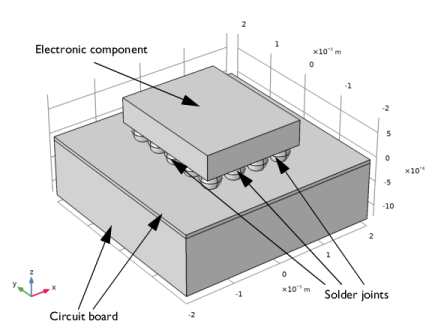
The geometry shown in Figure 1 represents a small part of a circuit board with an electronic component (chip) mounted by means of several solder ball joints.
Figure 1: Geometry consisting of an electronic component mounted on a circuit board.
Electronic components can experience high temperatures during prolonged time periods, which can lead to permanent deformation and failure of the solder joints due to creep in the material.
For a larger geometry, this phenomenon is studied in the model “Viscoplastic Creep in Solder Joints” found under Nonlinear Structural Mechanics Module>Viscoplasticity. Note, however, that running this model requires additional licenses.
Application Library path: COMSOL_Multiphysics/Meshing_Tutorials/meshing_sequence
Modeling Instructions
From the File menu, choose New.
New
In the New window, click  Model Wizard.
Model Wizard
1
In the Model Wizard window, click  3D.
2
Geometry 1
Insert the geometry sequence from the meshing_sequence_geom_sequence.mph file.
1
In the Geometry toolbar, click  Insert Sequence.
2
Block 1 (blk1)
1
In the Geometry toolbar, click  Build All.
2
Click the  Zoom Extents button in the Graphics toolbar.
Continue by creating a simple unstructured tetrahedral mesh.
Mesh 1
As you click the Mesh 1 node the Form Union feature is automatically built, which means that the various objects are combined into one object with domains separated by inner boundaries. This assures that a continuous mesh can be created across the unconnected but touching geometry objects that make up the geometry in this case.
With the default Physics-controlled mesh, in the Sequence type list in the Mesh settings window, COMSOL automatically creates a mesh adapted for the physics settings in the model. A set of nine predefined element sizes, ranging from Extremely fine to Extremely coarse and the default Normal size, give you control of how well you would like to resolve the geometry. With the default physics-controlled option the meshing sequence is always hidden.
1
In the Model Builder window, under Component 1 (comp1) click Mesh 1.
2
In the Settings window for Mesh, click  Build All.
According to information displayed in the Messages window this mesh consists of approximately 45,000 elements. While the geometry is resolved quite well by this mesh, you may want to reduce the number of elements to reduce the memory required for solving the problem.
In the following instructions you will manually modify the meshing sequence.
3
Locate the Mesh Settings section. From the Sequence type list, choose User-controlled mesh.
A default mesh sequence consisting of the Size and Free Tetrahedral 1 nodes appears under the Mesh 1 node.
The first Size feature node is called a global attribute feature, since it influences all subsequent operation features in the meshing sequence. This first Size feature node cannot be deleted from the meshing sequence. You can also add attribute features under an operation feature node, in which case it is called a local attribute feature.
Free Tetrahedral 1
Assume that you are investigating the solder joints and would therefore like to keep the detailed mesh in the spherical domains but create a mesh with fewer elements in the remaining domains.
Size 1
1
In the Model Builder window, right-click Free Tetrahedral 1 and choose Size.
2
In the Settings window for Size, locate the Element Size section.
3
From the Predefined list, choose Coarser.
4
Locate the Geometric Entity Selection section. From the Geometric entity level list, choose Domain.
5
6
Click  Build All.
According to the Messages window the mesh now consists of approximately 28,000 elements.
For even fewer elements in the circuit board and electronic component, you can create a swept mesh. This technique sweeps a boundary mesh through the domains to create a structured mesh in the sweep direction.
Free Tetrahedral 1
First you can modify the free tetrahedral mesh operation to apply on the solder joints, then disable the corresponding Size 1 node, as it is no longer needed.
1
In the Model Builder window, click Free Tetrahedral 1.
2
In the Settings window for Free Tetrahedral, locate the Domain Selection section.
3
From the Geometric entity level list, choose Domain.
4
5
Click  Build All.
Only the mesh of the solder joints is built this time
Size 1
1
In the Model Builder window, right-click Size 1 and choose Disable.
The swept mesher operates on a 3D domain by first meshing a source face, and then sweeping the resulting face mesh through the domain to an opposite destination face. For straight and circular sweep paths, you can use several connected faces as source faces. All faces that encompass a domain are classified as either source faces, a destination face, or linking faces. The linking faces are the faces connecting the source and destination faces.
Free Triangular 1
1
In the Model Builder window, right-click Mesh 1 and choose More Operations>Free Triangular.
Here, the sources for the swept mesh on domains 2 and 3 (the upper part of the circuit board and the electronic component) consist of several faces. Some of these faces are already meshed, as they form the boundary to the solder joints. By meshing faces 7 and 12, highlighted in the figure below, you can complete the source mesh for the mesh sweep operation that will follow.
The Free Triangular 1 feature node is added after the Free Tetrahedral 1 feature node. COMSOL Multiphysics always inserts new nodes in the meshing sequence after the current feature node. To indicate the current feature node, it appears with a quadratic frame around its icon. As soon as it is inserted, the Free Triangular 1 node becomes the current feature.
You can easily move nodes in the meshing sequence, but this could lead to build errors as operation can depend on earlier operations in the sequence. Test to move the Free Triangular 1 operation in the sequence.
To make selection of the faces easier activate wireframe rendering of the geometry.
2
3
In the Settings window for Free Triangular, click  Build All.
Note that the settings of the first global size attribute are applied by the mesher when creating the triangular mesh. For a coarser triangular mesh add a local size attribute to the free triangular mesh operation.
Size 1
1
Right-click Free Triangular 1 and choose Size.
2
In the Settings window for Size, locate the Element Size section.
3
From the Predefined list, choose Coarser.
4
Click  Build All.
The new triangular mesh looks almost the same as the previous one. The reason is that the local coarser size attribute applies only on the interior of the meshed faces. On the edges the mesher has to respect the already existing mesh on the solder joints, and, on the outer edges the global size settings, which is set to normal mesh size.
To avoid this situation a good practice is to set the first global Size setting to the coarsest mesh that you plan to have in the geometry, then specify local size feature nodes for the mesh operations that need finer mesh.
Size
1
In the Model Builder window, click Size.
2
In the Settings window for Size, locate the Element Size section.
3
From the Predefined list, choose Coarser.
Size 1
Since the global mesh size is now too coarse for the solder joints, enable the Size 1 feature under the Free Tetrahedral 1 node.
1
In the Model Builder window, right-click Size 1 and choose Enable.
2
In the Settings window for Size, locate the Geometric Entity Selection section.
3
From the Selection list, choose All domains.
4
5
Locate the Element Size section. From the Predefined list, choose Normal.
Size 1
The size attribute for the triangular mesh is no longer needed and can be removed.
In the Model Builder window, right-click Size 1 and choose Delete.
Free Triangular 1
1
In the Settings window for Free Triangular, click  Build All.
Notice that the triangular mesh is coarser this time.
Continue by sweeping the source mesh through the remaining domains.
Swept 1
1
In the Model Builder window, right-click Mesh 1 and choose Swept.
The Geometric entity level list is set to Remaining by default for new mesh operations. In this case the remaining domains correspond to the domains we would like to sweep mesh.
2
In the Settings window for Swept, click  Build All.
The mesh now consists of approximately 17,000 elements. The swept mesher used the Coarser predefined mesh size to determine the number of elements along the sweep direction. For precise control of the number of elements specify a distribution for the swept mesher.
Distribution 1
1
Right-click Swept 1 and choose Distribution.
2
In the Settings window for Distribution, locate the Distribution section.
3
In the Number of elements text field, type 2.
4
Click  Build All.
This latest mesh consists of approximately 21,000 elements, keeping the higher resolution for the domains that are important for the analysis, while providing a less dense structured mesh for the remaining domains.