PDF

On/Off Control of a Thermal Actuator
Introduction
This example model consists of a two-hot-arm thermal actuator made of polysilicon. The actuator is activated through thermal expansion. The temperature increase required to deform the two hot arms, and thus displace the actuator, is obtained through Joule heating (resistive heating). The greater expansion of the hot arms, compared to the cold arm, causes a bending of the actuator.
This is a modified version of the Thermal Microactuator Simplified model from the COMSOL Multiphysics Application Library. In the present model, the applied current is controlled so that the actuator deflection does not exceed a given value. The on/off controller used in this example is implemented in Simulink.
Model Definition
The electro-thermal expansion problem is solved in COMSOL Multiphysics, while the control system is implemented in Simulink as an on/off controller.
The cosimulation with COMSOL Multiphysics and Simulink is set up by exporting a COMSOL Cosimulation file from the COMSOL model and then adding this file to the COMSOL Cosimulation block in the Simulink simulation diagram. The input of the block consists of the applied voltage. The block has two outputs: the tip displacement, which is used as control variable, and the maximum temperature in the actuator.
Figure 1 shows the full control simulation diagram in Simulink.
Figure 1: Simulink diagram of the thermal actuator controller.
Results and Discussion
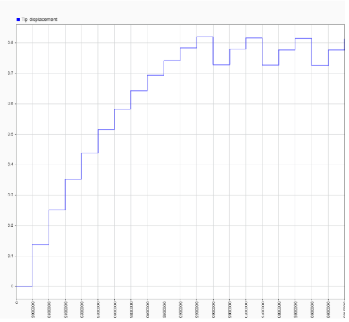
Figure 2 below shows the actuator tip displacement at the communication time between COMSOL and Simulink. The tip displacement is always controlled between 0.71 μm and 0.81 μm. To reduce the variation in the displacement, you need to reduce the communication time and the settings in the relay block.
Figure 2: Actuator tip displacement at communication.
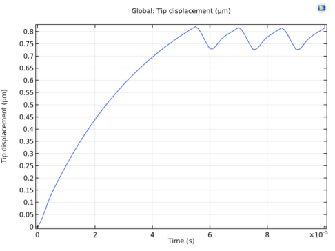
In COMSOL Multiphysics, the output time step used during the computation is set with a lower value than the communication time step. Figure 3 below shows the actuator tip displacement that is stored in the COMSOL model once the simulation is run. Notice that the results are much smoother.
Figure 3: Actuator tip displacement at computed time.
 
 
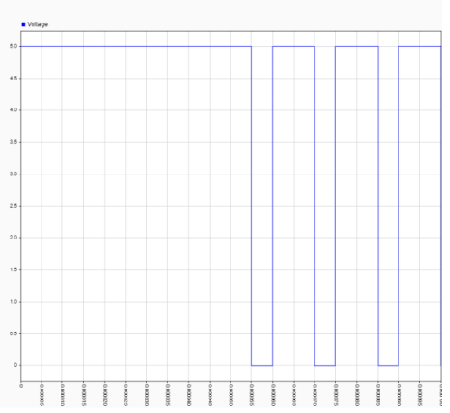
Figure 4 shows the applied voltage as an input to the COMSOL model. The plot clearly shows the on/off activation based on the tip displacement of the actuator.
Figure 4: Applied voltage vs. time.
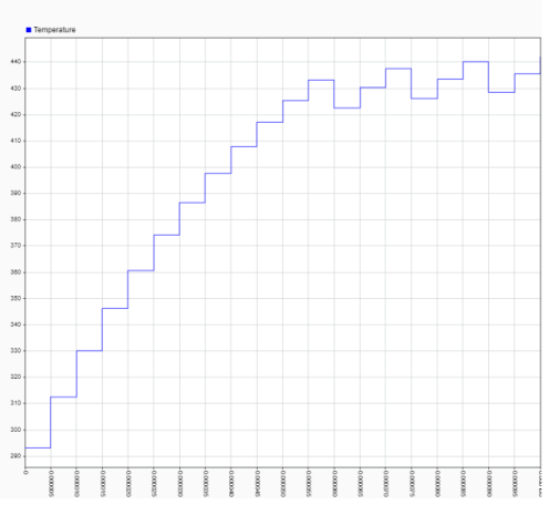
The maximum temperature in the actuator is shown in Figure 5. The activation intervals are too short for the cooling as the temperature keeps increasing.
Figure 5: Actuator maximum temperature vs. time.
Setting Up the Cosimulation
Follow the workflow below to set up the cosimulation with COMSOL Multiphysics and Simulink:
1
2
3
4
5
6
Application Library path: LiveLink_for_Simulink/Tutorials/thermal_actuator_llsimulink
Modeling Instructions — COMSOL Desktop
In this example you will start from an existing model which is an example in the COMSOL Multiphysics.
From the File menu, choose Open.
From the Application Libraries root, browse to the folder COMSOL_Multiphysics/Multiphysics and double-click the file thermal_actuator_simplified.mph.
Definitions
Domain Point Probe 1
1
In the Model Builder window, expand the Thermal Actuator (comp1) node.
2
Right-click Thermal Actuator (comp1)>Definitions and choose Probes>Domain Point Probe.
3
In the Settings window for Domain Point Probe, locate the Point Selection section.
4
In row Coordinates, set x to L.
5
Select the Snap to closest boundary check box.
Point Probe Expression 1 (ppb1)
1
In the Model Builder window, expand the Domain Point Probe 1 node, then click Point Probe Expression 1 (ppb1).
2
In the Settings window for Point Probe Expression, locate the Expression section.
3
In the Expression text field, type v.
Maximum 1 (maxop1)
1
In the Definitions toolbar, click  Nonlocal Couplings and choose Maximum.
2
In the Settings window for Maximum, locate the Source Selection section.
3
From the Selection list, choose All domains.
Variables 1
In the Model Builder window, right-click Definitions and choose Variables.
Solid Mechanics (solid)
Linear Elastic Material 1
In the Model Builder window, expand the Thermal Actuator (comp1)>Solid Mechanics (solid) node, then click Linear Elastic Material 1.
Damping 1
1
In the Physics toolbar, click  Attributes and choose Damping.
2
In the Settings window for Damping, locate the Damping Settings section.
3
In the αdM text field, type 1e-6.
4
In the βdK text field, type 1e-6.
Root
In the Home toolbar, click  Windows and choose Add Study.
Add Study
1
Go to the Add Study window.
2
Find the Studies subsection. In the Select Study tree, select General Studies>Time Dependent.
3
Click  Add Study.
4
In the Home toolbar, click  Add Study to close the Add Study window.
Study 2
Step 1: Time Dependent
1
In the Settings window for Time Dependent, locate the Study Settings section.
2
In the Output times text field, type range(0,1e-6,1e-4).
Solution 2 (sol2)
1
In the Study toolbar, click  Show Default Solver.
2
In the Model Builder window, expand the Solution 2 (sol2) node.
3
In the Model Builder window, expand the Study 2>Solver Configurations>Solution 2 (sol2)>Dependent Variables 1 node, then click Temperature (comp1.T).
4
In the Settings window for Field, locate the Scaling section.
5
From the Method list, choose Manual.
6
In the Scale text field, type 300.
7
In the Model Builder window, click Electric potential (comp1.V).
8
In the Settings window for Field, locate the Scaling section.
9
From the Method list, choose Manual.
10
In the Study toolbar, click  Compute.
Results
1D Plot Group 10
1
In the Home toolbar, click  Add Plot Group and choose 1D Plot Group.
2
In the Settings window for 1D Plot Group, locate the Data section.
3
From the Dataset list, choose Study 2/Solution 2 (sol2).
Global 1
1
Right-click 1D Plot Group 10 and choose Global.
2
In the Settings window for Global, locate the y-Axis Data section.
3
4
Click to expand the Legends section. Clear the Show legends check box.
Save the COMSOL Model
1
In the Model Builder window, click Temperature (ht) 1.
2
From the File menu, choose Save As.
3
Browse to a suitable folder, enter the filename thermal_actuator_llsimulink.mph, and then click Save.
Exporting the Cosimulation File
In the following configure the cosimulation, and export the file for cosimulation that will be loaded into Simulink.
Global Definitions
Cosimulation for Simulink 1
1
In the Study toolbar, click  Cosimulation for Simulink.
2
In the Settings window for Cosimulation for Simulink, locate the Filename section.
3
In the Filename text field, type thermal_actuator_llsimulink.
4
Locate the Inputs section. Click  Add.
5
6
Locate the Outputs section. In the table, enter the following settings:
7
Locate the Study section. From the Study list, choose Study 2.
8
Locate the Image section. Click Set from Graphics WindowThis sets the current temperature plot (if a solution is available) as the thumbnail used for the COMSOL Cosimulation block inside Simulink.
9
Click  Export.
Modeling Instructions — Simulink
Once you have created the COMSOL model and saved the cosimulation file you can start Simulink to continue with the setup there.
1
2
In MATLAB enter the command mphapplicationlibraries to start the GUI for viewing models from the LiveLink for Simulink application library.
3
4
The included COMSOL Cosimulation block is already configured with a cosimulation file based on the model from the COMSOL Application Library and ready to run. If you want to run the simulation directly, go to Step 7 below. Else, if you want to use the model file and cosimulation file you have created by following the steps in the section Modeling Instructions — COMSOL Desktop, you can continue with Step 5 below.
5
6
Note: In case the folder path of the file for cosimulation for Simulink is not set in MATLAB enter the full filename.
For this simulation the stop time is set to 104 s and the communication step size is set to 5 μs.
7
Postrocessing the Solution in the COMSOL Desktop
To reproduce Figure 3 follow the steps below:
1
Once you have run the simulation in Simulink, in the MATLAB prompt enter mphlaunch. This automatically start the COMSOL Desktop with the model loaded.
2
In the Model Builder, under Results select 1D Plot Group 10.
Note: Close the COMSOL Desktop before running a new simulation in Simulink.