PDF

Mechanical Modeling of Bentonite Clay
Introduction
The Barcelona Basic Model (BBM) is one of the most widely used constitutive models for representing hydromechanical behavior in partially saturated soils. In COMSOL Multiphysics, a modified version of the original model is implemented, the so-called Extended Barcelona Basic Model (BBMx) as described in Ref. 1. By including the suction as a state variable in the constitutive relationship, the BBM and BBMx models can describe partially saturated soils. As opposed to fully saturated soils, partially saturated soils can be loaded either hydraulically or mechanically, or by combination of both mechanisms.
This example validates the BBMx model implemented in COMSOL Multiphysics (Ref. 1) by qualitatively matching the results of mechanical modeling to results of the oedometer, triaxial and suction tests presented in Ref. 2 for bentonite clays. However, the experiments in Ref. 2 are set up to determine suitable material parameters to characterize the BBM model, and while the fundamental principles are the same, there are some differences between the BBM and BBMx models. In addition to the tests described in Ref. 2, an additional test of constrained swelling is carried out to compare the results with analytical formulas.
The Cam-Clay family of soil models, like the BBMx model, do not define any stiffness at zero stress, hence numerical simulations that use these soil models always prescribe an initial mean stress equal to the reference pressure at zero strain.
Model Definition
A cylindrical soil specimen of 3.91 cm in diameter and 8 cm in height is used for all tests. The specimen is represented by a 2D axisymmetric geometry due to the intrinsic symmetry of the problem.
For the oedometer test, initial stresses in the radial, circumferential and axial directions are applied. In the first stage, the bottom and side boundaries are constrained in the normal direction. In the second stage, an axial load is applied on the top boundary.
For the uniaxial swelling test, initial stresses in the radial, circumferential and axial directions are applied together with a constant load on the top boundary. The sample is then subjected to changes in suction.
For the triaxial test (Figure 1), an initial stress is applied to create a state of isotropic compression, the soil sample is then compressed further in the axial direction.
In the constrained swelling test, all boundaries are mechanically constrained, and the sample is then subjected to changes in suction.
Figure 1: Dimensions, boundary conditions, and boundary loads for the triaxial test.
Soil Properties
Soil properties from Ref. 2 that are used for the BBMx model are presented in Table 1..
ν
ρ
κ
κs
λ
λs
bs
ks
sy
e0
s0
pref
pc0
In COMSOL Multiphysics, either the void ratio at reference pressure together with the saturation eref0, or the initial void ratio e0 are needed as a material property. For this example, an initial void ratio is provided as an input material property.
For the oedometer and triaxial tests, the compression index at current suction is independent of the suction, since suction values are held constant in Ref. 2. To achieve this, the weight parameter is set to zero. In COMSOL Multiphysics, the formula for the compression index at current suction is implemented in a different way, therefore, the weight parameter is set to one in order to achieve the same effect as shown in Ref. 2. In these cases the choice of the soil stiffness parameter does not matter.
The yield function and the plastic potential used in COMSOL Multiphysics is different than the expressions given in Ref. 2. The nonassociative parameter for the plastic potential is always set to one in COMSOL Multiphysics as compared to Ref. 2.
Constraints and Loads
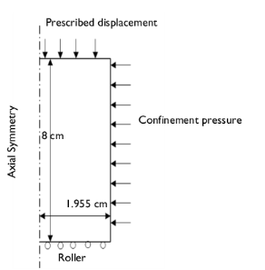
For the oedometer test, an initial stress of 2.97 MPa is applied in the radial and circumferential directions, while 0.18 MPa is applied in the axial direction.
Note that the reference pressure pref acts as an initial stress, therefore the values of the diagonal components of the in-situ stress tensor defined in the External Stress node are 2.87 MPa, 2.87 MPa, and 0.08 MPa.
During the loading stage of the oedometer test, the axial compressive stress is increased from 0.18 MPa to 19.77 MPa, and then decreased from 19.77 MPa to 1.00 MPa. Roller boundary conditions are applied on the bottom and side boundaries. The suction value is kept constant throughout the analysis.
For the uniaxial swelling test, an initial stress of 2.54 MPa is applied in the radial and circumferential directions, while 8.90 MPa is applied in the axial direction. The reference pressure pref acts as an initial stress, so the values of the diagonal components of the in-situ stress tensor in the External Stress node are -2.34 MPa, 2.34 MPa, and 8.70 MPa.
In the loading step of the uniaxial swelling test, the axial compressive stress is maintained constant at 8.90 MPa, while the suction is reduced from 101.5 MPa to 12.6 MPa. Roller boundary conditions are applied on the bottom and side boundaries.
For the triaxial test in isotropic compression, an initial hydrostatic stress of 1.1 MPa is applied. As the reference pressure pref acts as an initial stress, the values of the diagonal components of the in-situ stress tensor defined in the External Stress node are 1 MPa.
Results and Discussion
Note that for consistency with the geomechanics sign convention, compressive stress and strain is plotted along the positive axis in all figures, while tensile stress and strain is plotted along the negative axis.
The evolution of both the void ratio and the radial stress versus axial stress during the loading and unloading phases in the oedometer test are shown in Figure 2, and the evolution of both the deviatoric stress and the mean stress in Figure 3. The results of both phases of the test resembles the results shown in Ref. 2, but there are some differences mainly in the unloading phase. These differences may be attributed to the implementation of different yield functions and plastic potentials.
Figure 2: Evolution of void ratio and radial stress versus axial stress for the oedometer test.
Figure 3: Stress path in the p-q plane for the oedometer test.
The evolution of both the void ratio and the radial stress versus suction in the uniaxial swelling test are shown in Figure 4. Both curves match the numerical results given in Ref. 2. The evolution of the mean stress is shown in Figure 5. The void ratio, the radial stress, and the mean stress all level out at a suction around 80 MPa, which is also reported in Ref. 2. This behavior is due to the accumulation of plastic strains. Moreover, at the end of the suction cycle, the void ratio shows an increasing trend, and this behavior is also reported in Ref. 2.
The evolution of the volumetric strain and the deviatoric stress versus axial strain are shown in Figure 6 and Figure 7, respectively. These results show good qualitative agreement with the results presented in Ref. 2. The slight mismatch is anticipated due to the different implementation of the material models, given by the different definitions for the yield function and the plastic potential.
The stress path in the p-q plane for the triaxial test is shown in Figure 8. The deviatoric stress equals 0.3 MPa when the mean stress is 1.2 MPa. this stress state coincides with the initial yield surface. These are the same value as reported in Ref. 2.
For the constrained swelling stress, evolution of the mean stress versus suction is shown in Figure 9. This result matches exactly the analytical expression given by Equation 1 in the pure elastic range.
For the BBMx model, the evolution of the volumetric strain is given by
with and
For constrained swelling there is no change in volumetric strain, hence
Integrating this equation, and finding the integration constant based on the initial values, gives
(1) with
For the constrained swelling test, both the volumetric strain and the void ratio remain constant as suction changes; this is portrayed in Figure 10.
Figure 4: Evolution of void ratio and radial stress versus suction in the uniaxial swelling test.
Figure 5: Evolution of mean stress versus suction in the uniaxial swelling test.
Figure 6: Evolution of volumetric strain versus axial strain in the triaxial test.
Figure 7: Evolution of deviatoric stress versus axial strain in the triaxial test.
Figure 8: Stress path in the p-q plane for the triaxial test.
Figure 9: Evolution of mean stress versus suction in the constrained swelling test.
Figure 10: Evolution of volumetric strain and void ratio versus suction in the constrained swelling test.
Notes About the COMSOL Implementation
The in-situ stresses are the stresses in the soil sample in a strain-free configuration. There are two methods to account for in-situ stresses in COMSOL Multiphysics. One way is to create two stationary study steps or studies, with a combination of the Initial Stress and Strain and External Stress nodes. The second method is to use the in-situ stress option in the External Stress node with single study. This option gives initial stresses in the soil sample without imposing any strains. In this example, the second method is used to model the initial/in-situ stresses in the soil sample.
References
1. D. Pedroso and M. Farias, “Extended Barcelona Basic Model for unsaturated soil under cyclic loadings,” Computers and Geotechnics, vol. 38, no. 5, pp. 731–740, 2011.
2. O. Kristensson and M. Åkesson, “Mechanical modeling of MX-80 - Quick tools for BBM parameter analysis,” Physics and Chemistry of the Earth, vol. 33, pp. 5508–5515, 2008.
Application Library path: Geomechanics_Module/Verification_Examples/mechanical_modeling_of_bentonite_clay
Modeling Instructions
From the File menu, choose New.
New
In the New window, click  Model Wizard.
Model Wizard
1
In the Model Wizard window, click  2D Axisymmetric.
2
In the Select Physics tree, select Structural Mechanics>Solid Mechanics (solid).
3
Click  Add Physics.
4
5
Click  Study.
6
In the Select Study tree, select General Studies>Stationary.
7
Global Definitions
Parameters 1
1
In the Model Builder window, under Global Definitions click Parameters 1.
2
In the Settings window for Parameters, locate the Parameters section.
3
BBMx Material Parameters
1
In the Home toolbar, click  Parameters and choose Add>Parameters.
2
In the Settings window for Parameters, type BBMx Material Parameters in the Label text field.
3
Locate the Parameters section. Click  Load from File.
4
Browse to the model’s Application Libraries folder and double-click the file mechanical_modeling_of_bentonite_clay_oedometer_parameters.txt.
5
In the Home toolbar, click  Parameter Case.
6
In the Settings window for Case, type Oedometer Test Parameters in the Label text field.
7
In the Home toolbar, click  Parameter Case.
8
In the Settings window for Case, type Uniaxial Swelling Test Parameters in the Label text field.
9
Locate the Parameters section. Click  Load from File.
10
Browse to the model’s Application Libraries folder and double-click the file mechanical_modeling_of_bentonite_clay_uniaxial_swelling_parameters.txt.
11
In the Home toolbar, click  Parameter Case.
12
In the Settings window for Case, type Triaxial Test Parameters in the Label text field.
13
Locate the Parameters section. Click  Load from File.
14
Browse to the model’s Application Libraries folder and double-click the file mechanical_modeling_of_bentonite_clay_triaxial_parameters.txt.
15
In the Home toolbar, click  Parameter Case.
16
In the Settings window for Case, type Constrained Swelling Test Parameters in the Label text field.
17
Locate the Parameters section. Click  Load from File.
18
Browse to the model’s Application Libraries folder and double-click the file mechanical_modeling_of_bentonite_clay_constrained_swelling_parameters.txt.
Geometry 1
Rectangle 1 (r1)
1
In the Geometry toolbar, click  Rectangle.
2
In the Settings window for Rectangle, locate the Size and Shape section.
3
In the Width text field, type 1.955[cm].
4
In the Height text field, type 8[cm].
5
Click  Build Selected.
First set up a physics interfaces for each soil tests.
Solid Mechanics [Oedometer Test]
1
In the Model Builder window, under Component 1 (comp1) click Solid Mechanics (solid).
2
In the Settings window for Solid Mechanics, type Solid Mechanics [Oedometer Test] in the Label text field.
Elastoplastic Soil Material 1
1
In the Physics toolbar, click  Domains and choose Elastoplastic Soil Material.
The provided material data does not include the void ratio at reference pressure and saturation, instead it gives the initial void ratio. Hence, change the default option of the initial void ratio property to From material instead of deriving it from void ratio at reference pressure and saturation.
2
3
In the Settings window for Elastoplastic Soil Material, locate the Elastoplastic Soil Material section.
4
From the Material model list, choose Extended Barcelona Basic.
5
From the e0 list, choose From material.
6
In the s0 text field, type s0.
7
In the s text field, type s0.
8
In the pref text field, type pref.
9
In the pc0 text field, type pc0.
External Stress 1
1
In the Physics toolbar, click  Attributes and choose External Stress.
The oedometer test is carried out in two steps. The first step is needed to get the initial stress state of the sample, and the second step is a compressive loading. The initial stress state can be modeled using the In-situ stress option of the External Stress node.
2
In the Settings window for External Stress, locate the External Stress section.
3
From the Stress input list, choose In-situ stress.
4
5
In the σins table, enter the following settings:
Roller 1
1
In the Physics toolbar, click  Boundaries and choose Roller.
2
Instead of adding a boundary load on the top boundary, prescribe the displacement as a function of the axial stress.
Elastoplastic Soil Material 1
In the Model Builder window, collapse the Component 1 (comp1)>Solid Mechanics [Oedometer Test] (solid)>Elastoplastic Soil Material 1 node.
Definitions
Interpolation 1 (int1)
1
In the Home toolbar, click  Functions and choose Local>Interpolation.
2
In the Settings window for Interpolation, locate the Definition section.
3
In the Function name text field, type sigmaZ.
4
5
Locate the Units section. In the Arguments text field, type 1.
6
In the Function text field, type MPa.
Average 1 (aveop1)
1
In the Definitions toolbar, click  Nonlocal Couplings and choose Average.
2
3
In the Settings window for Average, locate the Advanced section.
4
From the Frame list, choose Material  (R, PHI, Z).
5
Clear the Compute integral in revolved geometry check box.
Solid Mechanics [Oedometer Test] (solid)
Prescribed Displacement 1
1
In the Physics toolbar, click  Boundaries and choose Prescribed Displacement.
2
3
In the Settings window for Prescribed Displacement, locate the Prescribed Displacement section.
4
Select the Prescribed in z direction check box.
5
In the u0z text field, type disp1.
Add a global equation to compute the axial displacement, so that the axial stress equals the reaction force for such a prescribed displacement. Show the advanced physics options to add a global equation.
6
Click the  Show More Options button in the Model Builder toolbar.
7
In the Show More Options dialog box, in the tree, select the check box for the node Physics>Equation-Based Contributions.
8
Global Equations 1
1
In the Physics toolbar, click  Global and choose Global Equations.
Multiply the global equation by a suitable penalty factor in order to strictly satisfy this equation. For the current model, 1e5 is an appropriate penalty factor.
2
In the Settings window for Global Equations, locate the Global Equations section.
3
4
Locate the Units section. Click  Select Dependent Variable Quantity.
5
In the Physical Quantity dialog box, type disp in the text field.
6
Click  Filter.
7
In the tree, select General>Displacement (m).
8
9
In the Settings window for Global Equations, locate the Units section.
10
Click  Select Source Term Quantity.
11
In the Physical Quantity dialog box, type pressure in the text field.
12
Click  Filter.
13
In the tree, select General>Pressure (Pa).
14
Definitions
Interpolation 2 (int2)
1
In the Home toolbar, click  Functions and choose Local>Interpolation.
2
In the Settings window for Interpolation, locate the Definition section.
3
In the Function name text field, type suction.
4
5
Locate the Units section. In the Arguments text field, type 1.
6
In the Function text field, type MPa.
Solid Mechanics [Uniaxial Swelling Test]
1
In the Model Builder window, under Component 1 (comp1) click Solid Mechanics 2 (solid2).
2
In the Settings window for Solid Mechanics, type Solid Mechanics [Uniaxial Swelling Test] in the Label text field.
Elastoplastic Soil Material 1
1
In the Physics toolbar, click  Domains and choose Elastoplastic Soil Material.
2
3
In the Settings window for Elastoplastic Soil Material, locate the Elastoplastic Soil Material section.
4
From the Material model list, choose Extended Barcelona Basic.
5
From the e0 list, choose From material.
6
In the s0 text field, type s0.
7
In the s text field, type suction(para).
8
In the pref text field, type pref.
9
In the pc0 text field, type pc0.
External Stress 1
1
In the Physics toolbar, click  Attributes and choose External Stress.
The uniaxial swelling test is carried out in two steps. The first step is needed to get the initial stress state of the sample, and the second step is a reduction in the suction while keeping a constant axial stress. The initial stress state can be modeled using the In-situ stress option of the External Stress node.
2
In the Settings window for External Stress, locate the External Stress section.
3
From the Stress input list, choose In-situ stress.
4
5
In the σins table, enter the following settings:
Roller 1
1
In the Physics toolbar, click  Boundaries and choose Roller.
2
Prescribed Displacement 1
1
In the Physics toolbar, click  Boundaries and choose Prescribed Displacement.
2
3
In the Settings window for Prescribed Displacement, locate the Prescribed Displacement section.
4
Select the Prescribed in z direction check box.
5
In the u0z text field, type disp2.
Global Equations 1
1
In the Physics toolbar, click  Global and choose Global Equations.
2
In the Settings window for Global Equations, locate the Global Equations section.
3
4
Locate the Units section. Click  Select Dependent Variable Quantity.
5
In the Physical Quantity dialog box, type disp in the text field.
6
Click  Filter.
7
In the tree, select General>Displacement (m).
8
9
In the Settings window for Global Equations, locate the Units section.
10
Click  Select Source Term Quantity.
11
In the Physical Quantity dialog box, type pressure in the text field.
12
Click  Filter.
13
In the tree, select General>Pressure (Pa).
14
Solid Mechanics [Triaxial Test]
1
In the Model Builder window, under Component 1 (comp1) click Solid Mechanics 3 (solid3).
2
In the Settings window for Solid Mechanics, type Solid Mechanics [Triaxial Test] in the Label text field.
Elastoplastic Soil Material 1
1
In the Physics toolbar, click  Domains and choose Elastoplastic Soil Material.
2
3
In the Settings window for Elastoplastic Soil Material, locate the Elastoplastic Soil Material section.
4
From the Material model list, choose Extended Barcelona Basic.
5
From the e0 list, choose From material.
6
In the s0 text field, type s0.
7
In the s text field, type s0.
8
In the pref text field, type pref.
9
In the pc0 text field, type pc0.
External Stress 1
1
In the Physics toolbar, click  Attributes and choose External Stress.
The triaxial test is carried out in two steps. The first step is needed to get the initial stress state of the sample, and the second step is an axial compressive loading. The initial stress state can be modeled using the In-situ stress option of the External Stress node.
2
In the Settings window for External Stress, locate the External Stress section.
3
From the Stress input list, choose In-situ stress.
4
In the σins text field, type -1[MPa].
Roller 1
1
In the Physics toolbar, click  Boundaries and choose Roller.
2
Prescribed Displacement 1
1
In the Physics toolbar, click  Boundaries and choose Prescribed Displacement.
2
3
In the Settings window for Prescribed Displacement, locate the Prescribed Displacement section.
4
Select the Prescribed in z direction check box.
5
In the u0z text field, type -disp3.
Solid Mechanics [Constrained Swelling Test]
1
In the Model Builder window, under Component 1 (comp1) click Solid Mechanics 4 (solid4).
2
In the Settings window for Solid Mechanics, type Solid Mechanics [Constrained Swelling Test] in the Label text field.
Elastoplastic Soil Material 1
1
In the Physics toolbar, click  Domains and choose Elastoplastic Soil Material.
2
3
In the Settings window for Elastoplastic Soil Material, locate the Elastoplastic Soil Material section.
4
From the Material model list, choose Extended Barcelona Basic.
5
From the e0 list, choose From material.
6
In the s0 text field, type s0.
7
In the s text field, type suction(para).
8
In the pref text field, type pref.
9
In the pc0 text field, type pc0.
Roller 1
1
In the Physics toolbar, click  Boundaries and choose Roller.
2
Definitions
Variables 1
1
In the Model Builder window, under Component 1 (comp1) right-click Definitions and choose Variables.
2
In the Settings window for Variables, locate the Variables section.
3
Materials
MX-80 Bentonite Clay
1
In the Model Builder window, under Component 1 (comp1) right-click Materials and choose Blank Material.
2
In the Settings window for Material, type MX-80 Bentonite Clay in the Label text field.
3
Locate the Material Contents section. In the table, enter the following settings:
Mesh 1
Mapped 1
In the Mesh toolbar, click  Mapped.
Only using a few mesh elements is sufficient for this analysis.
Distribution 1
1
Right-click Mapped 1 and choose Distribution.
2
In the Settings window for Distribution, locate the Boundary Selection section.
3
From the Selection list, choose All boundaries.
4
Locate the Distribution section. In the Number of elements text field, type 6.
5
Click  Build Selected.
Set up the studies for all tests.
Add Study
1
In the Home toolbar, click  Add Study to open the Add Study window.
2
Go to the Add Study window.
3
Find the Studies subsection. In the Select Study tree, select General Studies>Stationary.
4
Click  Add Study.
5
In the Select Study tree, select General Studies>Stationary.
6
Click  Add Study.
7
In the Select Study tree, select General Studies>Stationary.
8
Click  Add Study.
9
In the Home toolbar, click  Add Study to close the Add Study window.
Study [Oedometer Test]
1
In the Settings window for Study, type Study [Oedometer Test] in the Label text field.
2
Locate the Study Settings section. Clear the Generate default plots check box.
Parametric Sweep
1
In the Study toolbar, click  Parametric Sweep.
2
In the Settings window for Parametric Sweep, locate the Study Settings section.
3
4
From the Sweep type list, choose Parameter switch.
5
6
Step 1: Stationary
1
In the Model Builder window, click Step 1: Stationary.
2
In the Settings window for Stationary, locate the Physics and Variables Selection section.
3
In the table, clear the Solve for check boxes for Solid Mechanics [Uniaxial Swelling Test] (solid2), Solid Mechanics [Triaxial Test] (solid3), and Solid Mechanics [Constrained Swelling Test] (solid4).
4
Click to expand the Study Extensions section. Select the Auxiliary sweep check box.
5
6
Use appropriate scaling and the Constant (Newton) nonlinear method to improve convergence.
Solution 1 (sol1)
1
In the Study toolbar, click  Show Default Solver.
2
In the Model Builder window, expand the Solution 1 (sol1) node.
3
In the Model Builder window, expand the Study [Oedometer Test]>Solver Configurations>Solution 1 (sol1)>Dependent Variables 1 node, then click State variable disp1 (comp1.ODE1).
4
In the Settings window for State, locate the Scaling section.
5
From the Method list, choose Manual.
6
In the Scale text field, type 1e-3.
7
In the Model Builder window, expand the Study [Oedometer Test]>Solver Configurations>Solution 1 (sol1)>Stationary Solver 1 node, then click Fully Coupled 1.
8
In the Settings window for Fully Coupled, click to expand the Method and Termination section.
9
From the Nonlinear method list, choose Constant (Newton).
10
From the Stabilization and acceleration list, choose Anderson acceleration.
11
In the Study toolbar, click  Compute.
Study [Uniaxial Swelling Test]
1
In the Model Builder window, click Study 2.
2
In the Settings window for Study, type Study [Uniaxial Swelling Test] in the Label text field.
3
Locate the Study Settings section. Clear the Generate default plots check box.
Parametric Sweep
1
In the Study toolbar, click  Parametric Sweep.
2
In the Settings window for Parametric Sweep, locate the Study Settings section.
3
From the Sweep type list, choose Parameter switch.
4
5
Step 1: Stationary
1
In the Model Builder window, click Step 1: Stationary.
2
In the Settings window for Stationary, locate the Physics and Variables Selection section.
3
In the table, clear the Solve for check boxes for Solid Mechanics [Oedometer Test] (solid), Solid Mechanics [Triaxial Test] (solid3), and Solid Mechanics [Constrained Swelling Test] (solid4).
4
Click to expand the Study Extensions section. Select the Auxiliary sweep check box.
5
6
7
In the Study toolbar, click  Compute.
Study [Triaxial Test]
1
In the Model Builder window, click Study 3.
2
In the Settings window for Study, type Study [Triaxial Test] in the Label text field.
3
Locate the Study Settings section. Clear the Generate default plots check box.
Parametric Sweep
1
In the Study toolbar, click  Parametric Sweep.
2
In the Settings window for Parametric Sweep, locate the Study Settings section.
3
From the Sweep type list, choose Parameter switch.
4
5
Step 1: Stationary
1
In the Model Builder window, click Step 1: Stationary.
2
In the Settings window for Stationary, locate the Physics and Variables Selection section.
3
In the table, clear the Solve for check boxes for Solid Mechanics [Oedometer Test] (solid), Solid Mechanics [Uniaxial Swelling Test] (solid2), and Solid Mechanics [Constrained Swelling Test] (solid4).
4
Click to expand the Study Extensions section. Select the Auxiliary sweep check box.
5
6
Use the Constant (Newton) nonlinear method to improve convergence.
Solution 7 (sol7)
1
In the Study toolbar, click  Show Default Solver.
2
In the Model Builder window, expand the Solution 7 (sol7) node.
3
In the Model Builder window, expand the Study [Triaxial Test]>Solver Configurations>Solution 7 (sol7)>Stationary Solver 1 node, then click Fully Coupled 1.
4
In the Settings window for Fully Coupled, click to expand the Method and Termination section.
5
From the Nonlinear method list, choose Constant (Newton).
6
From the Stabilization and acceleration list, choose Anderson acceleration.
7
In the Study toolbar, click  Compute.
Study [Constrained Swelling Test]
1
In the Model Builder window, click Study 4.
2
In the Settings window for Study, type Study [Constrained Swelling Test] in the Label text field.
3
Locate the Study Settings section. Clear the Generate default plots check box.
Parametric Sweep
1
In the Study toolbar, click  Parametric Sweep.
2
In the Settings window for Parametric Sweep, locate the Study Settings section.
3
From the Sweep type list, choose Parameter switch.
4
5
Step 1: Stationary
1
In the Model Builder window, click Step 1: Stationary.
2
In the Settings window for Stationary, locate the Physics and Variables Selection section.
3
In the table, clear the Solve for check boxes for Solid Mechanics [Oedometer Test] (solid), Solid Mechanics [Uniaxial Swelling Test] (solid2), and Solid Mechanics [Triaxial Test] (solid3).
4
Click to expand the Study Extensions section. Select the Auxiliary sweep check box.
5
6
Use the Constant (Newton) nonlinear method to improve convergence.
Solution 10 (sol10)
1
In the Study toolbar, click  Show Default Solver.
2
In the Model Builder window, expand the Solution 10 (sol10) node.
3
In the Model Builder window, expand the Study [Constrained Swelling Test]>Solver Configurations>Solution 10 (sol10)>Stationary Solver 1 node, then click Fully Coupled 1.
4
In the Settings window for Fully Coupled, click to expand the Method and Termination section.
5
From the Nonlinear method list, choose Constant (Newton).
6
In the Study toolbar, click  Compute.
Results
Evolution of Void Ratio and Radial Stress with Axial Stress [Oedometer Test]
1
In the Home toolbar, click  Add Plot Group and choose 1D Plot Group.
2
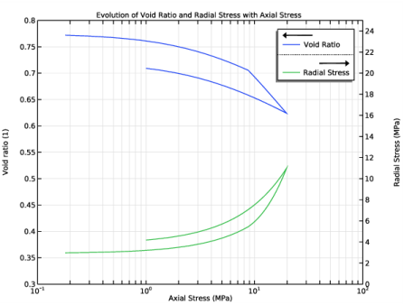
In the Settings window for 1D Plot Group, type Evolution of Void Ratio and Radial Stress with Axial Stress [Oedometer Test] in the Label text field.
3
Click to expand the Title section. From the Title type list, choose Manual.
4
In the Title text area, type Evolution of Void Ratio and Radial Stress with Axial Stress.
5
Click to collapse the Title section. Locate the Plot Settings section. Select the Two y-axes check box.
6
Select the x-axis label check box.
7
8
Select the Secondary y-axis label check box.
9
10
Locate the Axis section. Select the Manual axis limits check box.
11
In the x minimum text field, type 0.1.
12
In the x maximum text field, type 100.
13
In the y minimum text field, type 0.3.
14
In the y maximum text field, type 0.8.
15
In the Secondary y minimum text field, type 0.
16
In the Secondary y maximum text field, type 25.
17
Select the x-axis log scale check box.
Point Graph 1
1
Right-click Evolution of Void Ratio and Radial Stress with Axial Stress [Oedometer Test] and choose Point Graph.
2
3
In the Settings window for Point Graph, locate the y-Axis Data section.
4
In the Expression text field, type solid.evoid.
5
Locate the x-Axis Data section. From the Parameter list, choose Expression.
6
In the Expression text field, type -solid.SZZ.
7
From the Unit list, choose MPa.
8
Click to expand the Legends section. Select the Show legends check box.
9
From the Legends list, choose Manual.
10
Point Graph 2
1
Right-click Point Graph 1 and choose Duplicate.
2
In the Settings window for Point Graph, locate the y-Axis Data section.
3
In the Expression text field, type -solid.SRR.
4
From the Unit list, choose MPa.
5
Locate the y-Axis section. Select the Plot on secondary y-axis check box.
6
Locate the Legends section. In the table, enter the following settings:
7
In the Evolution of Void Ratio and Radial Stress with Axial Stress [Oedometer Test] toolbar, click  Plot.
Stress Path in p-q Plane [Oedometer Test]
1
In the Home toolbar, click  Add Plot Group and choose 1D Plot Group.
2
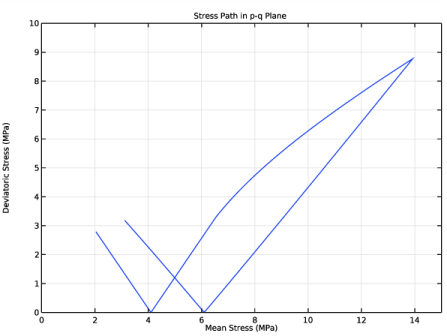
In the Settings window for 1D Plot Group, type Stress Path in p-q Plane [Oedometer Test] in the Label text field.
3
Click to expand the Title section. From the Title type list, choose Manual.
4
In the Title text area, type Stress Path in p-q Plane.
5
Locate the Plot Settings section. Select the x-axis label check box.
6
7
Select the y-axis label check box.
8
In the associated text field, type Deviatoric Stress (MPa).
9
Locate the Axis section. Select the Manual axis limits check box.
10
In the x minimum text field, type 0.
11
In the x maximum text field, type 15.
12
In the y minimum text field, type 0.
13
In the y maximum text field, type 10.
Point Graph 1
1
Right-click Stress Path in p-q Plane [Oedometer Test] and choose Point Graph.
2
3
In the Settings window for Point Graph, locate the y-Axis Data section.
4
In the Expression text field, type solid.mises.
5
From the Unit list, choose MPa.
6
Locate the x-Axis Data section. From the Parameter list, choose Expression.
7
In the Expression text field, type solid.pm.
8
From the Unit list, choose MPa.
9
In the Stress Path in p-q Plane [Oedometer Test] toolbar, click  Plot.
Evolution of Void Ratio and Radial Stress with Suction [Uniaxial Swelling Test]
1
In the Home toolbar, click  Add Plot Group and choose 1D Plot Group.
2
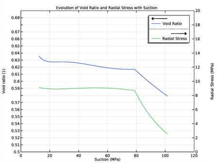
In the Settings window for 1D Plot Group, type Evolution of Void Ratio and Radial Stress with Suction [Uniaxial Swelling Test] in the Label text field.
3
Locate the Data section. From the Dataset list, choose Study [Uniaxial Swelling Test]/Solution 4 (sol4).
4
Locate the Title section. From the Title type list, choose Manual.
5
In the Title text area, type Evolution of Void Ratio and Radial Stress with Suction.
6
Click to collapse the Title section. Locate the Plot Settings section. Select the Two y-axes check box.
7
Select the x-axis label check box.
8
9
Select the Secondary y-axis label check box.
10
11
Locate the Axis section. Select the Manual axis limits check box.
12
In the x minimum text field, type 0.
13
In the x maximum text field, type 120.
14
In the y minimum text field, type 0.5.
15
In the y maximum text field, type 0.7.
16
In the Secondary y minimum text field, type 0.
17
In the Secondary y maximum text field, type 20.
Point Graph 1
1
Right-click Evolution of Void Ratio and Radial Stress with Suction [Uniaxial Swelling Test] and choose Point Graph.
2
3
In the Settings window for Point Graph, locate the y-Axis Data section.
4
In the Expression text field, type solid2.evoid.
5
Locate the x-Axis Data section. From the Parameter list, choose Expression.
6
In the Expression text field, type solid2.ss.
7
From the Unit list, choose MPa.
8
Locate the Legends section. Select the Show legends check box.
9
From the Legends list, choose Manual.
10
Point Graph 2
1
Right-click Point Graph 1 and choose Duplicate.
2
In the Settings window for Point Graph, locate the y-Axis Data section.
3
In the Expression text field, type -solid2.SRR.
4
From the Unit list, choose MPa.
5
Locate the y-Axis section. Select the Plot on secondary y-axis check box.
6
Locate the Legends section. In the table, enter the following settings:
7
In the Evolution of Void Ratio and Radial Stress with Suction [Uniaxial Swelling Test] toolbar, click  Plot.
Evolution of Mean Stress with Suction [Uniaxial Swelling Test]
1
In the Home toolbar, click  Add Plot Group and choose 1D Plot Group.
2
In the Settings window for 1D Plot Group, type Evolution of Mean Stress with Suction [Uniaxial Swelling Test] in the Label text field.
3
Locate the Data section. From the Dataset list, choose Study [Uniaxial Swelling Test]/Solution 4 (sol4).
4
Click to expand the Title section. From the Title type list, choose Manual.
5
In the Title text area, type Evolution of Mean Stress with Suction.
6
Click to collapse the Title section. Locate the Plot Settings section. Select the x-axis label check box.
7
8
Select the y-axis label check box.
9
10
Locate the Axis section. Select the Manual axis limits check box.
11
In the x minimum text field, type 0.
12
In the x maximum text field, type 120.
13
In the y minimum text field, type 0.
14
In the y maximum text field, type 20.
Point Graph 1
1
Right-click Evolution of Mean Stress with Suction [Uniaxial Swelling Test] and choose Point Graph.
2
3
In the Settings window for Point Graph, locate the y-Axis Data section.
4
In the Expression text field, type solid2.pm.
5
From the Unit list, choose MPa.
6
Locate the x-Axis Data section. From the Parameter list, choose Expression.
7
In the Expression text field, type solid2.ss.
8
From the Unit list, choose MPa.
9
In the Evolution of Mean Stress with Suction [Uniaxial Swelling Test] toolbar, click  Plot.
Stress Path in p-q Plane [Uniaxial Swelling Test]
1
In the Home toolbar, click  Add Plot Group and choose 1D Plot Group.
2
In the Settings window for 1D Plot Group, type Stress Path in p-q Plane [Uniaxial Swelling Test] in the Label text field.
3
Locate the Data section. From the Dataset list, choose Study [Uniaxial Swelling Test]/Solution 4 (sol4).
4
Click to expand the Title section. From the Title type list, choose Manual.
5
In the Title text area, type Stress Path in p-q Plane.
6
Locate the Plot Settings section. Select the x-axis label check box.
7
8
Select the y-axis label check box.
9
In the associated text field, type Deviatoric Stress (MPa).
10
Locate the Axis section. Select the Manual axis limits check box.
11
In the x minimum text field, type 0.
12
In the x maximum text field, type 10.
13
In the y minimum text field, type 0.
14
In the y maximum text field, type 8.
Point Graph 1
1
Right-click Stress Path in p-q Plane [Uniaxial Swelling Test] and choose Point Graph.
2
3
In the Settings window for Point Graph, locate the y-Axis Data section.
4
In the Expression text field, type solid2.mises.
5
From the Unit list, choose MPa.
6
Locate the x-Axis Data section. From the Parameter list, choose Expression.
7
In the Expression text field, type solid2.pm.
8
From the Unit list, choose MPa.
9
In the Stress Path in p-q Plane [Uniaxial Swelling Test] toolbar, click  Plot.
Evolution of Volumetric Strain with Axial Strain [Triaxial Test]
1
In the Home toolbar, click  Add Plot Group and choose 1D Plot Group.
2
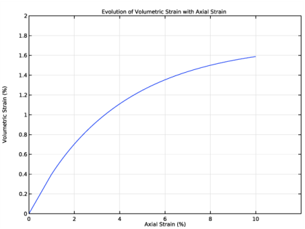
In the Settings window for 1D Plot Group, type Evolution of Volumetric Strain with Axial Strain [Triaxial Test] in the Label text field.
3
Locate the Data section. From the Dataset list, choose Study [Triaxial Test]/Solution 7 (sol7).
4
Locate the Title section. From the Title type list, choose Manual.
5
In the Title text area, type Evolution of Volumetric Strain with Axial Strain.
6
Locate the Plot Settings section. Select the x-axis label check box.
7
8
Select the y-axis label check box.
9
10
Locate the Axis section. Select the Manual axis limits check box.
11
In the x minimum text field, type 0.
12
In the x maximum text field, type 12.
13
In the y minimum text field, type 0.
14
In the y maximum text field, type 2.
Point Graph 1
1
Right-click Evolution of Volumetric Strain with Axial Strain [Triaxial Test] and choose Point Graph.
2
3
In the Settings window for Point Graph, locate the y-Axis Data section.
4
In the Expression text field, type -solid3.evol.
5
From the Unit list, choose %.
6
Locate the x-Axis Data section. From the Parameter list, choose Expression.
7
In the Expression text field, type -solid3.eZZ.
8
From the Unit list, choose %.
9
In the Evolution of Volumetric Strain with Axial Strain [Triaxial Test] toolbar, click  Plot.
Evolution of Deviatoric Stress with Axial Strain [Triaxial Test]
1
In the Home toolbar, click  Add Plot Group and choose 1D Plot Group.
2
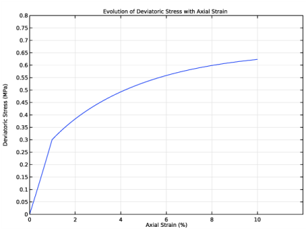
In the Settings window for 1D Plot Group, type Evolution of Deviatoric Stress with Axial Strain [Triaxial Test] in the Label text field.
3
Locate the Data section. From the Dataset list, choose Study [Triaxial Test]/Solution 7 (sol7).
4
Locate the Title section. From the Title type list, choose Manual.
5
In the Title text area, type Evolution of Deviatoric Stress with Axial Strain.
6
Locate the Plot Settings section. Select the x-axis label check box.
7
8
Select the y-axis label check box.
9
In the associated text field, type Deviatoric Stress (MPa).
10
Locate the Axis section. Select the Manual axis limits check box.
11
In the x minimum text field, type 0.
12
In the x maximum text field, type 12.
13
In the y minimum text field, type 0.
14
In the y maximum text field, type 0.8.
Point Graph 1
1
Right-click Evolution of Deviatoric Stress with Axial Strain [Triaxial Test] and choose Point Graph.
2
3
In the Settings window for Point Graph, locate the y-Axis Data section.
4
In the Expression text field, type solid3.mises.
5
From the Unit list, choose MPa.
6
Locate the x-Axis Data section. From the Parameter list, choose Expression.
7
In the Expression text field, type -solid3.eZZ.
8
From the Unit list, choose %.
9
In the Evolution of Deviatoric Stress with Axial Strain [Triaxial Test] toolbar, click  Plot.
Stress Path in p-q Plane [Triaxial Test]
1
In the Home toolbar, click  Add Plot Group and choose 1D Plot Group.
2
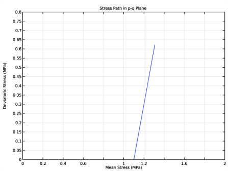
In the Settings window for 1D Plot Group, type Stress Path in p-q Plane [Triaxial Test] in the Label text field.
3
Locate the Data section. From the Dataset list, choose Study [Triaxial Test]/Solution 7 (sol7).
4
Locate the Title section. From the Title type list, choose Manual.
5
In the Title text area, type Stress Path in p-q Plane.
6
Locate the Plot Settings section. Select the x-axis label check box.
7
8
Select the y-axis label check box.
9
In the associated text field, type Deviatoric Stress (MPa).
10
Locate the Axis section. Select the Manual axis limits check box.
11
In the x minimum text field, type 0.
12
In the x maximum text field, type 2.
13
In the y minimum text field, type 0.
14
In the y maximum text field, type 0.8.
Point Graph 1
1
Right-click Stress Path in p-q Plane [Triaxial Test] and choose Point Graph.
2
3
In the Settings window for Point Graph, locate the y-Axis Data section.
4
In the Expression text field, type solid3.mises.
5
From the Unit list, choose MPa.
6
Locate the x-Axis Data section. From the Parameter list, choose Expression.
7
In the Expression text field, type solid3.pm.
8
From the Unit list, choose MPa.
9
In the Stress Path in p-q Plane [Triaxial Test] toolbar, click  Plot.
Evolution of Mean Stress with Suction [Constrained Swelling Test]
1
In the Home toolbar, click  Add Plot Group and choose 1D Plot Group.
2
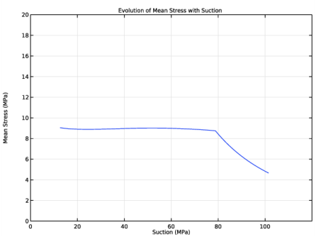
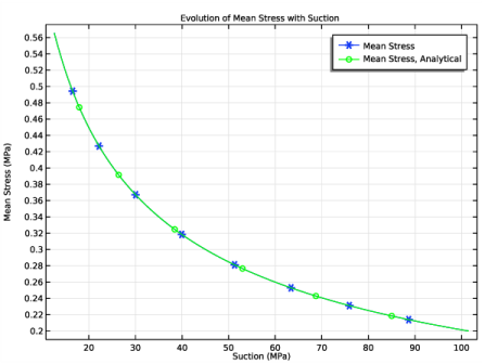
In the Settings window for 1D Plot Group, type Evolution of Mean Stress with Suction [Constrained Swelling Test] in the Label text field.
3
Locate the Title section. From the Title type list, choose Manual.
4
In the Title text area, type Evolution of Mean Stress with Suction.
5
Locate the Data section. From the Dataset list, choose Study [Constrained Swelling Test]/Solution 10 (sol10).
6
Locate the Plot Settings section. Select the x-axis label check box.
7
8
Select the y-axis label check box.
9
Point Graph 1
1
Right-click Evolution of Mean Stress with Suction [Constrained Swelling Test] and choose Point Graph.
2
3
In the Settings window for Point Graph, locate the y-Axis Data section.
4
In the Expression text field, type solid4.pm.
5
From the Unit list, choose MPa.
6
Locate the x-Axis Data section. From the Parameter list, choose Expression.
7
In the Expression text field, type solid4.ss.
8
From the Unit list, choose MPa.
9
Click to expand the Coloring and Style section. Find the Line markers subsection. From the Marker list, choose Asterisk.
10
Locate the Legends section. Select the Show legends check box.
11
From the Legends list, choose Manual.
12
Point Graph 2
1
Right-click Point Graph 1 and choose Duplicate.
2
In the Settings window for Point Graph, locate the y-Axis Data section.
3
In the Expression text field, type P_analytical.
4
Locate the Legends section. In the table, enter the following settings:
5
Locate the Coloring and Style section. From the Color list, choose Green.
6
Find the Line markers subsection. From the Marker list, choose Circle.
7
In the Number text field, type 6.
8
In the Evolution of Mean Stress with Suction [Constrained Swelling Test] toolbar, click  Plot.
Evolution of Voulmetric Strain and Void Ratio with Suction [Constrained Swelling Test]
1
In the Home toolbar, click  Add Plot Group and choose 1D Plot Group.
2
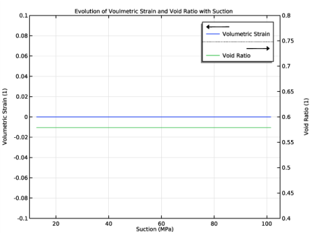
In the Settings window for 1D Plot Group, type Evolution of Voulmetric Strain and Void Ratio with Suction in the Label text field.
3
Locate the Data section. From the Dataset list, choose Study [Constrained Swelling Test]/Solution 10 (sol10).
4
In the Label text field, type Evolution of Voulmetric Strain and Void Ratio with Suction [Constrained Swelling Test].
5
Locate the Title section. From the Title type list, choose Manual.
6
In the Title text area, type Evolution of Voulmetric Strain and Void Ratio with Suction.
7
Locate the Plot Settings section. Select the Two y-axes check box.
8
Select the x-axis label check box.
9
10
Select the y-axis label check box.
11
12
Select the Secondary y-axis label check box.
13
14
Locate the Axis section. Select the Manual axis limits check box.
15
In the x minimum text field, type 10.
16
In the x maximum text field, type 105.
17
In the y minimum text field, type -0.1.
18
In the y maximum text field, type 0.1.
19
In the Secondary y minimum text field, type 0.4.
20
In the Secondary y maximum text field, type 0.8.
Point Graph 1
1
Right-click Evolution of Voulmetric Strain and Void Ratio with Suction [Constrained Swelling Test] and choose Point Graph.
2
3
In the Settings window for Point Graph, locate the y-Axis Data section.
4
In the Expression text field, type solid4.evol.
5
Locate the x-Axis Data section. From the Parameter list, choose Expression.
6
In the Expression text field, type solid4.ss.
7
From the Unit list, choose MPa.
8
Locate the Legends section. Select the Show legends check box.
9
From the Legends list, choose Manual.
10
Point Graph 2
1
Right-click Point Graph 1 and choose Duplicate.
2
In the Settings window for Point Graph, locate the y-Axis Data section.
3
In the Expression text field, type solid4.evoid.
4
Locate the y-Axis section. Select the Plot on secondary y-axis check box.
5
Locate the Legends section. In the table, enter the following settings:
Evolution of Voulmetric Strain and Void Ratio with Suction [Constrained Swelling Test]
1
In the Model Builder window, collapse the Results>Evolution of Voulmetric Strain and Void Ratio with Suction [Constrained Swelling Test] node.
2
In the Model Builder window, click Evolution of Voulmetric Strain and Void Ratio with Suction [Constrained Swelling Test].
3
In the Evolution of Voulmetric Strain and Void Ratio with Suction [Constrained Swelling Test] toolbar, click  Plot.