PDF

Stray Current Pipeline Corrosion
Introduction
The impressed current cathodic protection (ICCP) system is often employed to mitigate corrosion of buried pipelines in oil and gas industry. Metallic objects such as buried pipelines, which are present within the current flow of the ICCP system, may suffer from the stray current interactions leading to accelerated corrosion.
The present model example demonstrates stray current corrosion of a buried pipeline, which is in vicinity of the ICCP system, using the Current Distribution, Boundary Elements interface. The ICCP system is considered to consist of a protected pipeline and an anode. An interference pipeline is considered to be in vicinity of the protected pipeline and is affected due to stray current.
The example is based on a paper by G. Cui and others (Ref. 1).
Model Definition
The model geometry is shown in Figure 1.
Figure 1: Model geometry consists of three line segments representing the anode, protected pipeline, and interference pipeline, which are surrounded by soil domain.
The model geometry consists of the protected pipeline, interference pipeline, and anode. Both the protected and interference pipelines are 1.6 km long and cross each other at an angle of 90° and at middle of their lengths. The protected pipeline diameter is 0.762 m, the interference pipeline diameter is 0.4064 m and the anode diameter is 0.1 m. The anode is 100 m away from the protected pipeline and 800 m away from the interference pipeline.
The two crossing pipelines and anode are considered to be the edge electrodes. The Current Distribution, Boundary Elements interface is used to solve for the electrolyte potential, (SI unit: V), over the edge domains according to:
where il (SI unit: A/m2) is the electrolyte current density vector and σl (SI unit: S/m) is the electrolyte conductivity which is 0.005 S/m for the soil domain.
At the anode edge, the applied current density is prescribed using the Electrolyte Current Density node as:
where n is the normal vector, pointing out of the domain and iapp is 1.528 A/m2.
At the protected and interference pipelines, kinetics of electrochemical reactions is prescribed using the Edge Electrode node as:
where f() is an interpolation function obtained form the experimental polarization data available in corrosion material library (Ref. 1).
For the interference pipeline, the electric potential model is set to floating potential with zero applied current, which indicates that the interference pipeline is electrically not connected to anything and it will interact with adjacent soil domain only through the electrochemical reactions occurring at the pipeline surface.
Results and Discussion
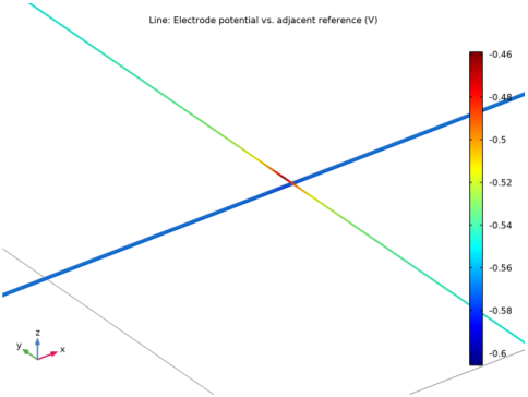
Figure 2 shows the electrode potential distribution over the protected and interference pipelines in the region closer to the pipelines crossing. It can be seen that the electrode potential over the protected pipeline is below its equilibrium potential (0.56 V) indicating that the pipeline is fully protected. The electrode potential over the interference pipeline is above its equilibrium potential (0.56 V), particularly in the region closer to the pipeline crossing, indicating the occurrence of corrosion.
Figure 2: The electrode potential distribution over the protected and interference pipelines in the region closer to the pipelines crossing.
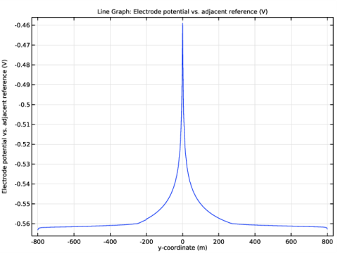
Figure 3 shows the electrode potential distribution over the entire length of the interference pipeline. It confirms the behavior seen in Figure 2 that the electrode potential is above its equilibrium potential in the region closer to the pipeline crossing (about 200 m on either side), indicating the occurrence of corrosion. It can also be seen in Figure 3 that the electrode potential further away from the pipeline crossing is below the equilibrium potential, indicating that the interference pipeline is protected in that region.
Figure 3: The electrode potential distribution over the entire length of the interference pipeline.
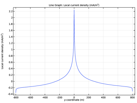
Figure 4 shows the local current density distribution over the entire length of the interference pipeline, and Figure 5 the same data depicted as an arrow line plot in the geometry in a close-up around the pipeline crossing. The local current density in the region closer to the pipeline crossing (about 200 m on either side) is positive (anodic) whereas the same away from the pipeline crossing is negative (cathodic). The interference pipeline is found to receive cathodic protection in terms of stray current in the region away from the pipelines crossing. The stray current leaves the interference pipe in a region closer to the pipelines crossing confirming, indicating corrosion in that region.
Figure 4: The local current density distribution over the entire length of the interference pipeline.
Figure 5: The local stray current density distribution depicted as an arrow line plot in the z-direction close to the pipe crossing.
Notes About the COMSOL Implementation
The model is implemented using the Current Distribution, Boundary Elements interface. Note that the governing equations are solved only over the edge domains, comprising the anode, protected pipeline, and interference pipeline; hence, only edge domains are discretized (meshed) in the model.
References
1. G. Cui, Z. Li, C. Yang and M. Wang, “The influence of DC stray current on pipeline corrosion”, Petroleum Science, vol. 13, pp. 135–145, 2016.
Application Library path: Corrosion_Module/Galvanic_Corrosion/stray_current
Modeling Instructions
From the File menu, choose New.
New
In the New window, click  Model Wizard.
Model Wizard
1
In the Model Wizard window, click  3D.
2
In the Select Physics tree, select Electrochemistry>Primary and Secondary Current Distribution>Current Distribution, Boundary Elements (cdbem).
3
Click Add.
4
Click  Study.
5
In the Select Study tree, select General Studies>Stationary.
6
Global Definitions
Parameters 1
First, load the model parameters.
1
In the Model Builder window, under Global Definitions click Parameters 1.
2
In the Settings window for Parameters, locate the Parameters section.
3
Click  Load from File.
4
Geometry 1
The model geometry consists of three line segments representing the anode, protected pipe and interference pipe, respectively.
Anode
1
In the Geometry toolbar, click  More Primitives and choose Line Segment.
2
In the Settings window for Line Segment, locate the Starting Point section.
3
From the Specify list, choose Coordinates.
4
In the x text field, type -lpipe/2.
5
In the y text field, type -100.
6
In the z text field, type -1.
7
Locate the Endpoint section. From the Specify list, choose Coordinates.
8
In the x text field, type -lpipe/2.
9
In the y text field, type -100.
10
In the z text field, type -1-lanode.
11
Locate the Selections of Resulting Entities section. Select the Resulting objects selection check box.
12
In the Label text field, type Anode.
Pipeline 1 (Protected)
1
In the Geometry toolbar, click  More Primitives and choose Line Segment.
2
In the Settings window for Line Segment, type Pipeline 1 (Protected) in the Label text field.
3
Locate the Starting Point section. From the Specify list, choose Coordinates.
4
In the x text field, type -lpipe/2.
5
In the z text field, type -4.
6
Locate the Endpoint section. From the Specify list, choose Coordinates.
7
In the x text field, type lpipe/2.
8
In the z text field, type -4.
9
Locate the Selections of Resulting Entities section. Select the Resulting objects selection check box.
Pipeline 2 (Interferrence)
1
In the Geometry toolbar, click  More Primitives and choose Line Segment.
2
In the Settings window for Line Segment, type Pipeline 2 (Interferrence) in the Label text field.
3
Locate the Starting Point section. From the Specify list, choose Coordinates.
4
In the y text field, type -lpipe/2.
5
In the z text field, type -2.
6
Locate the Endpoint section. From the Specify list, choose Coordinates.
7
In the y text field, type lpipe/2.
8
In the z text field, type -2.
9
Locate the Selections of Resulting Entities section. Select the Resulting objects selection check box.
10
Click  Build All Objects.
11
Click the  Zoom Extents button in the Graphics toolbar.
Your geometry should like this.
Materials
Use the Corrosion Material Library to set up the material properties for the electrode kinetics at the Q235 steel electrode surface.
Add Material
1
In the Home toolbar, click  Add Material to open the Add Material window.
2
Go to the Add Material window.
3
In the tree, select Corrosion>Iron Alloys (Steels)>Q235 steel in soil.
4
Click Add to Component in the window toolbar.
Current Distribution, Boundary Elements (cdbem)
Now, set up the physics of the model. Start with selecting the reference electrode. Then, set the electrolyte conductivity, set the applied current density at the anode and electrochemical reaction kinetics at the two pipelines.
1
In the Model Builder window, under Component 1 (comp1) click Current Distribution, Boundary Elements (cdbem).
2
In the Settings window for Current Distribution, Boundary Elements, click to expand the Physics vs. Materials Reference Electrode Potential section.
3
From the list, choose 0.314 V (CSE vs. SHE).
Electrolyte 1
1
In the Model Builder window, under Component 1 (comp1)>Current Distribution, Boundary Elements (cdbem) click Electrolyte 1.
2
In the Settings window for Electrolyte, locate the Electrolyte section.
3
In the σl text field, type sigma.
Electrolyte Current Density 1
1
In the Physics toolbar, click  Edges and choose Electrolyte Current Density.
2
In the Settings window for Electrolyte Current Density, locate the Edge Selection section.
3
From the Selection list, choose Anode.
4
Locate the Electrolyte Current Density section. In the in,l text field, type iapp.
Edge Electrode 1
1
In the Physics toolbar, click  Edges and choose Edge Electrode.
2
In the Settings window for Edge Electrode, locate the Edge Selection section.
3
From the Selection list, choose Pipeline 1 (Protected).
4
Locate the Edge Radius section. In the Edge radius text field, type rpipe1.
5
Locate the Electric Potential section. From the Electric potential model list, choose Fixed.
Electrode Reaction 1
1
In the Model Builder window, expand the Edge Electrode 1 node, then click Electrode Reaction 1.
2
In the Settings window for Electrode Reaction, locate the Electrode Kinetics section.
3
From the iloc,expr list, choose From material.
Edge Electrode 2
1
In the Model Builder window, under Component 1 (comp1)>Current Distribution, Boundary Elements (cdbem) right-click Edge Electrode 1 and choose Duplicate.
2
In the Settings window for Edge Electrode, locate the Edge Selection section.
3
From the Selection list, choose Pipeline 2 (Interferrence).
4
Locate the Edge Radius section. In the Edge radius text field, type rpipe2.
5
Locate the Electric Potential section. From the Electric potential model list, choose Floating potential.
Mesh 1
Set the fine mesh at all line segments.
1
In the Model Builder window, under Component 1 (comp1) click Mesh 1.
2
In the Settings window for Mesh, locate the Mesh Settings section.
3
From the Sequence type list, choose User-controlled mesh.
Size 1
1
In the Model Builder window, right-click Edge 1 and choose Size.
2
In the Settings window for Size, locate the Element Size section.
3
Click the Custom button.
4
Locate the Element Size Parameters section. Select the Maximum element size check box.
5
6
Click  Build All.
The mesh should look like this.
Study 1
The model is now ready to be solved.
1
In the Home toolbar, click  Compute.
Results
Some plots are generated by default.
Electrode Potential vs. Adjacent Reference (cdbem)
One can zoom in a region closer to intersection of the two pipelines using a Zoom Box to visualize the electrode potential variation along the pipelines.
1
In the Model Builder window, click Electrode Potential vs. Adjacent Reference (cdbem).
2
In the Electrode Potential vs. Adjacent Reference (cdbem) toolbar, click  Plot.
The plot should look like Figure 2.
Electrode Potential
Now, plot the electrode potential and local current density variation along the interferrence pipe.
1
In the Home toolbar, click  Add Plot Group and choose 1D Plot Group.
2
In the Settings window for 1D Plot Group, type Electrode Potential in the Label text field.
Line Graph 1
1
In the Electrode Potential toolbar, click  Line Graph.
2
In the Settings window for Line Graph, locate the Selection section.
3
From the Selection list, choose Pipeline 2 (Interferrence).
4
Click Replace Expression in the upper-right corner of the y-Axis Data section. From the menu, choose Component 1 (comp1)>Current Distribution, Boundary Elements>cdbem.Evsref - Electrode potential vs. adjacent reference - V.
5
Locate the x-Axis Data section. From the Parameter list, choose Expression.
6
In the Expression text field, type y.
7
In the Electrode Potential toolbar, click  Plot.
The plot should look like Figure 3.
Local current density
1
In the Model Builder window, right-click Electrode Potential and choose Duplicate.
2
In the Settings window for 1D Plot Group, type Local current density in the Label text field.
Line Graph 1
1
In the Model Builder window, expand the Local current density node, then click Line Graph 1.
2
In the Settings window for Line Graph, click Replace Expression in the upper-right corner of the y-Axis Data section. From the menu, choose Component 1 (comp1)>Current Distribution, Boundary Elements>Electrode kinetics>cdbem.iloc_er1 - Local current density - A/m².
3
Locate the y-Axis Data section. In the Unit field, type mA/m^2.
4
In the Local current density toolbar, click  Plot.
The plot should look like Figure 4.
Electrolyte Current Density (cdbem)
Follow the instructions below to reproduce the plot in Figure 5.
Stray Current Density
1
In the Model Builder window, right-click Electrolyte Current Density (cdbem) and choose Duplicate.
2
In the Settings window for 3D Plot Group, type Stray Current Density in the Label text field.
Line 1
1
In the Model Builder window, expand the Stray Current Density node, then click Line 1.
2
In the Settings window for Line, click Replace Expression in the upper-right corner of the Expression section. From the menu, choose Component 1 (comp1)>Current Distribution, Boundary Elements>Electrode kinetics>cdbem.iloc_er1 - Local current density - A/m².
3
Click to expand the Title section. From the Title type list, choose None.
Selection 1
1
Right-click Line 1 and choose Selection.
2
In the Settings window for Selection, locate the Selection section.
3
From the Selection list, choose Pipeline 2 (Interferrence).
Line 2
1
Right-click Line 1 and choose Duplicate.
2
In the Settings window for Line, locate the Expression section.
3
In the Expression text field, type 1.
4
Locate the Coloring and Style section. From the Coloring list, choose Uniform.
5
From the Color list, choose Gray.
Selection 1
1
In the Model Builder window, expand the Line 2 node, then click Selection 1.
2
In the Settings window for Selection, locate the Selection section.
3
From the Selection list, choose Pipeline 1 (Protected).
Arrow Line 1
1
In the Model Builder window, right-click Stray Current Density and choose Arrow Line.
2
In the Settings window for Arrow Line, locate the Expression section.
3
In the X component text field, type 0.
4
In the Y component text field, type 0.
5
In the Z component text field, type cdbem.iloc_er1.
6
Click to expand the Title section. From the Title type list, choose Manual.
7
In the Title text area, type Arrow Line: Local current density (A/m<sup>2</sup>).
8
Click to expand the Inherit Style section. From the Plot list, choose Line 1.
Selection 1
1
Right-click Arrow Line 1 and choose Selection.
2
In the Settings window for Selection, locate the Selection section.
3
From the Selection list, choose Pipeline 2 (Interferrence).
Color Expression 1
1
In the Model Builder window, right-click Arrow Line 1 and choose Color Expression.
2
In the Settings window for Color Expression, click Replace Expression in the upper-right corner of the Expression section. From the menu, choose cdbem.iloc_er1 - Local current density - A/m².
Stray Current Density
1
Click the  Zoom Out button in the Graphics toolbar.
2
In the Model Builder window, click Stray Current Density.
3
In the Stray Current Density toolbar, click  Plot.
The plot should look like Figure 5.