PDF

Transonic Flow in a Sajben Diffuser
Introduction
In the present example the high speed turbulent gas flow in a converging and diverging nozzle is modeled using the High Mach Number Flow interface. The diffuser is transonic in the sense that the flow at the inlet is subsonic, but due to the contraction and the low outlet pressure, the flow accelerates and becomes sonic (Ma = 1) in the throat of the nozzle. After a short region of supersonic flow, a normal shock wave brings the flow back to subsonic flow. This setup has been studied in a number of experiments and numerical simulations by M. Sajben and co-workers (see for example Ref. 1, Ref. 2, Ref. 3, and Ref. 4), in an effort to study unsteady fluctuations in supersonic inlets with applications in supersonic aircraft propulsion systems. The geometry and setup is often referred to as a Sajben diffuser and constitutes a common test case for the simulation of high Mach number internal flows. In this example, the time-averaged transonic flow through a Sajben diffuser is solved for using two different exit pressures. The flow in the diffuser is fully turbulent with a inlet Reynolds number of × 105 based on the inlet fluid properties and the channel height. The model uses the Spalart-Allmaras turbulence model to compute the turbulent viscosity. For the first outlet pressure value a normal shock is present, but the flow remains attached throughout the diverging part. For the second, lower, outlet pressure value, the shock is strong enough to cause a shock-induced separation in the diverging part. Based on the ability to induce flow separation, the shock in the first case is referred to as weak, while in the second case it is termed strong following the definition in Ref. 2.
Model Definition
Figure 1 shows the physical geometry of the converging and diverging nozzle model. The nozzle dimensions correspond to those used in the experiments in Ref. 2 and in the benchmarks simulation of Ref. 5 and Ref. 6. In the central contraction part, the minimum vertical height separating the lower and upper walls, the throat height hth, is 1.7322 in (44 mm). The channel height at the inlet is 1.4hth, and the outlet height is 1.5hth.
Figure 1: Geometry and dimensions of the Sajben diffuser model.
Fluid Properties
The fluid occupying the channel is assumed to be air, by specifying a specific gas constant of 287 J/(kg·K) and a ratio of specific heats of 1.4. The dynamic viscosity is computed using Sutherland’s Law:
where the Tref = 500 R (about 278 K) corresponds to the inlet total temperature, and the Sutherland constant is Sμ = 111 K. The reference viscosity μref is defined from the inlet Reynolds number:
which in turn is used in a parametric sweep, where the model is solved for increasing Reynolds number. The final inlet Reynolds number to be computed is × 105, corresponding to the one used in the simulation in Ref. 5. The thermal conductivity of the gas is defined using the definition of the Prandtl number
which is assumed to be 0.71 in this case. This is a typical number for air around 293 K.
Boundary Conditions
Inlet Condition
The flow at the inlet is subsonic with a flow speed corresponding to a Mach number of 0.46. The inlet conditions are specified in terms of total properties, where the total pressure is defined as 19.58 psi and the total temperature is 500 R. The inlet conditions are applied using an Inlet feature, where the Flow condition is specified to be Characteristics based. This provides a numerically consistent boundary condition by evaluating the flow characteristics at the inlet (for more background on this boundary condition, see the CFD Module User’s Guide).
Outlet Condition
At the outlet the static pressure is specified. The model is solved for the two outlet pressure values specified in Table 1 below.
These outlet pressure values are known from experiments and simulations to be low enough to produce sonic conditions at the throat of the nozzle. However, they are not low enough for the flow to stay supersonic throughout the diverging part. The supersonic flow in the divergent part is terminated by a normal shock wave, so that the flow in the following part including the outlet becomes subsonic. The pressure is specified in the model using an Outlet node with the Flow condition set to Subsonic.
Results and Discussion
Below, some of the results from the transonic diffuser model computed in COMSOL Multiphysics are shown and discussed. The results are compared to experimental data from Ref. 2 (strong shock case) and Ref. 4 (weak shock case). The experimental data was extracted as tabulated data from Ref. 5 and Ref. 6 and plotted in COMSOL using interpolation functions.
Figure 2 shows the Mach numbers and velocity streamlines resulting from applying the first outlet pressure, 16.05 psi. It can be seen that the flow accelerates in the converging part, reaches sonic conditions at the throat, after which a region of supersonic flow follows in the diverging part. The supersonic region is terminated by a normal shock wave, which brings the flow back to subsonic conditions. In the remaining part of the channel the flow decelerates subsonically toward the outlet. The zero contour of the x-component velocity is also plotted in the figure, but this is only present on the walls and not visible inside the domain. Hence no separation zone is present, and the flow remains attached throughout the divergent part of the channel. The shock is not able to cause flow separation and is therefore termed weak. These results correlate well with those in Ref. 2 and Ref. 5.
Figure 2: Mach number, flow streamlines, and zero x-component velocity contour resulting from the weak shock case.
Figure 3 shows the same quantities as Figure 2, but uses the results from the second outlet pressure case, pout = 14.10 psi. Due to the lower outlet pressure, the normal shock wave is positioned further downstream in the divergent channel part. More importantly, a flow separation zone can be seen behind the shock, as indicated by the zero x-component velocity contour. The shock wave in this case is apparently strong enough to induce flow separation. This result is in accordance with those presented in Ref. 2 and Ref. 6.
Figure 3: Mach number, flow streamlines, and zero x-component velocity contour (in red) resulting from the strong shock case.
Figure 4 shows the development of the static pressure on the upper wall normalized by the inlet total pressure. Results from both the weak and strong cases are plotted and compared with the experimental data of Ref. 1 and Ref. 2. The results from both outlet cases are in general in very good agreement with the experimental results in the diffuser. Note however that the shock positions in the model are slightly shifted in the downstream direction in comparison with the experiments.
For analysis of the results in the interior of the channel, Figure 5 plots the streamwise velocity profiles from the strong shock case at two different positions in the divergent part of the channel together with experimental results. The velocity profile at the first position, x = 4.611hth, compares very well with the experimental results. Both the velocity magnitude and the size of the separation zone, including reversed flow, are accurately reproduced. Further downstream, at the x = 6.340hth position, the velocity magnitude in the central part of the channel is also in good agreement with the experimental results. Closer to the upper wall, the model results include flow reversal at this position. This is not found in the experimental result, indicating that the separation zone in the model extends further downstream than that in the experiment.
Figure 4: Top wall static pressure normalized by the inlet total pressure. Model results (lines) and experimental results (diamonds) are shown.
Figure 5: Mean x-component velocity at two positions downstream of the strong shock. Model results (lines) and experimental results (diamonds) are shown.
Notes About the COMSOL Implementation
The present model is highly nonlinear and sensitive to the solution procedure. The sensitivity is accentuated by the fact that the model seeks to determine the equilibrium position of a normal shock wave, positioned in a channel with smoothly varying channel height.
You solve the model in two steps. First, apply the higher outlet pressure to simulate the weak shock case. To solve this case, use a parametric sweep where the inlet Reynolds number increases stepwise by decreasing the dynamic viscosity. When you have obtained a converged result for the highest Reynolds number, use this solution as the initial condition for the second case with the lower outlet pressure value. In both cases, use pseudo-time stepping with manually defined CFL number expressions to compute stationary solutions.
References
1. M. Sajben, J.C. Kroutil, and C.P. Chen, “A High-Speed Schlieren Investigation of Diffuser Flows with Dynamic Distortion”, AIAA Paper 77-875, 1977.
2. T.J. Bogar, M. Sajben, and J.C. Kroutil, “Characteristic Frequencies of Transonic Diffuser Flow Oscillations,” AIAA Journal, vol. 21, no. 9, pp. 1232–1240, 1983.
3. J.T. Salmon, T.J. Bogar, and M. Sajben, “Laser Doppler Velocimetry in Unsteady, Separated, Transonic Flow,” AIAA Journal, vol. 21, no. 12, pp. 1690–1697, 1983.
4. T. Hsieh, A.B. Wardlaw Jr., T.J. Bogar, P. Collins, and T. Coakley, “Numerical Investigation of Unsteady Inlet Flowfields,” AIAA Journal, vol. 25, no. 1, pp. 75–81, 1987.
5. NPARC Alliance Validation Archive, “Sajben Transonic Diffuser: Study #1,”, 2008, http://www.grc.nasa.gov/WWW/wind/valid/transdif/transdif01/transdif01.html
6. NPARC Alliance Validation Archive, “Sajben Transonic Diffuser: Study #2,”, 2008, http://www.grc.nasa.gov/WWW/wind/valid/transdif/transdif02/transdif02.html
Application Library path: CFD_Module/High_Mach_Number_Flow/sajben_diffuser
Modeling Instructions
From the File menu, choose New.
New
In the New window, click  Model Wizard.
Model Wizard
1
In the Model Wizard window, click  2D.
2
In the Select Physics tree, select Fluid Flow>High Mach Number Flow>Turbulent Flow>High Mach Number Flow, Spalart-Allmaras (hmnf).
3
Click Add.
4
Click  Study.
5
In the Select Study tree, select Preset Studies for Selected Physics Interfaces>Stationary with Initialization.
6
Global Definitions
Geometry parameters
1
In the Model Builder window, under Global Definitions click Parameters 1.
2
In the Settings window for Parameters, locate the Parameters section.
3
4
Right-click Global Definitions>Parameters 1 and choose Rename.
5
In the Rename Parameters dialog box, type Geometry parameters in the New label text field.
6
Fluid flow parameters
1
In the Home toolbar, click  Parameters and choose Add>Parameters.
2
In the Settings window for Parameters, type Fluid flow parameters in the Label text field.
3
Locate the Parameters section. In the table, enter the following settings:
Interpolation 1 (int1)
1
In the Home toolbar, click  Functions and choose Global>Interpolation.
2
In the Settings window for Interpolation, locate the Definition section.
3
From the Data source list, choose File.
4
Find the Functions subsection. In the table, enter the following settings:
5
Click Browse.
6
7
Click Import.
8
Locate the Units section. In the Function text field, type in.
Interpolation 2 (int2)
1
In the Home toolbar, click  Functions and choose Global>Interpolation.
2
In the Settings window for Interpolation, locate the Definition section.
3
From the Data source list, choose File.
4
Find the Functions subsection. In the table, enter the following settings:
5
Click Browse.
6
7
Click Import.
Interpolation 3 (int3)
1
In the Home toolbar, click  Functions and choose Global>Interpolation.
2
In the Settings window for Interpolation, locate the Definition section.
3
From the Data source list, choose File.
4
Find the Functions subsection. In the table, enter the following settings:
5
Click Browse.
6
7
Click Import.
Interpolation 4 (int4)
1
In the Home toolbar, click  Functions and choose Global>Interpolation.
2
In the Settings window for Interpolation, locate the Definition section.
3
From the Data source list, choose File.
4
Find the Functions subsection. In the table, enter the following settings:
5
Click Browse.
6
7
Click Import.
Interpolation 5 (int5)
1
In the Home toolbar, click  Functions and choose Global>Interpolation.
2
In the Settings window for Interpolation, locate the Definition section.
3
From the Data source list, choose File.
4
Find the Functions subsection. In the table, enter the following settings:
5
Click Browse.
6
7
Click Import.
Definitions
Variables 1
1
In the Home toolbar, click  Variables and choose Local Variables.
2
In the Settings window for Variables, locate the Variables section.
3
The manual CFL number expression for the strong shock corresponds to the implemented automatic expression for turbulent flows. In this case the solution already contains a shock that will move due to the change in the outlet pressure, and a cautious increase of the CFL number is needed. In the weak case simulation, a shock is not yet formed, and the simulation time can be reduced by using a more aggressive ramping of the CFL number.
Geometry 1
Parametric Curve 1 (pc1)
1
In the Geometry toolbar, click  More Primitives and choose Parametric Curve.
2
In the Settings window for Parametric Curve, locate the Parameter section.
3
In the Minimum text field, type x0[1/in].
4
In the Maximum text field, type xEnd[1/in].
5
Locate the Expressions section. In the x text field, type s[in].
6
In the y text field, type top_pos(s).
7
Click  Build Selected.
Polygon 1 (pol1)
1
In the Geometry toolbar, click  Polygon.
2
In the Settings window for Polygon, locate the Object Type section.
3
From the Type list, choose Open curve.
4
Locate the Coordinates section. From the Data source list, choose Vectors.
5
In the x text field, type x0 x0 x0 xEnd xEnd xEnd.
6
In the y text field, type h_in 0 0 0 0 h_out.
7
Click  Build Selected.
Convert to Solid 1 (csol1)
1
In the Geometry toolbar, click  Conversions and choose Convert to Solid.
2
Click in the Graphics window and then press Ctrl+A to select both objects.
3
In the Settings window for Convert to Solid, click  Build Selected.
Add a rectangular domain in the divergent part of the nozzle. This will be used to increase the resolution in the region where the shock is located.
Rectangle 1 (r1)
1
In the Geometry toolbar, click  Rectangle.
2
In the Settings window for Rectangle, locate the Size and Shape section.
3
In the Width text field, type 0.16.
4
In the Height text field, type 0.1.
5
Locate the Position section. In the x text field, type 0.025.
6
Click  Build Selected.
Partition Objects 1 (par1)
1
In the Geometry toolbar, click  Booleans and Partitions and choose Partition Objects.
2
3
In the Settings window for Partition Objects, locate the Partition Objects section.
4
Find the Tool objects subsection. Select the  Activate Selection toggle button.
5
6
Click  Build Selected.
Add a Mesh Control Edges feature to specify the interior boundaries as mesh control entities. In this manner these entities can be used to control the mesh, but at the same time they will automatically be omitted when defining the physics and when postprocessing results.
Mesh Control Edges 1 (mce1)
1
In the Geometry toolbar, click  Virtual Operations and choose Mesh Control Edges.
2
On the object fin, select Boundaries 3 and 5 only.
It might be easier to select the boundaries by using the Selection List window. To open this window, in the Home toolbar click Windows and choose Selection List. (If you are running the cross-platform desktop, you find Windows in the main menu).
3
In the Geometry toolbar, click  Build All.
High Mach Number Flow, Spalart-Allmaras (hmnf)
Fluid 1
1
In the Model Builder window, under Component 1 (comp1)>High Mach Number Flow, Spalart-Allmaras (hmnf) click Fluid 1.
2
In the Settings window for Fluid, locate the Heat Conduction section.
3
From the k list, choose User defined. In the associated text field, type hmnf.Cp*hmnf.mu/Pr.
Here the conductivity is defined using a constant Prandtl number.
4
Locate the Thermodynamics section. From the Rs list, choose User defined. In the associated text field, type Rs.
5
From the Specify Cp or γ list, choose Ratio of specific heats.
6
From the γ list, choose User defined. In the associated text field, type gamma.
7
Locate the Dynamic Viscosity section. In the μref text field, type mu_ref.
8
In the Tμ,ref text field, type Tin_stat.
Initial Values 1
1
In the Model Builder window, click Initial Values 1.
2
In the Settings window for Initial Values, locate the Initial Values section.
3
Specify the u vector as
4
In the p text field, type pin_stat.
5
In the nutilde text field, type subst(hmnf.nutildeinit,p,pin_stat).
This ensures that when evaluating the initial condition for nutilde, the pressure used corresponds to pin_stat.
6
In the T text field, type Tin_stat.
Inlet 1
1
In the Physics toolbar, click  Boundaries and choose Inlet.
2
3
In the Settings window for Inlet, locate the Flow Properties section.
4
From the Input state list, choose Total.
5
In the p0,tot text field, type pin_tot.
6
In the T0,tot text field, type Tin_tot.
7
In the Ma0 text field, type Min.
Outlet 1
1
In the Physics toolbar, click  Boundaries and choose Outlet.
2
3
In the Settings window for Outlet, locate the Flow Condition section.
4
From the Flow condition list, choose Subsonic.
5
Locate the Flow Properties section. From the Boundary condition list, choose Pressure.
6
In the p0 text field, type pOut.
CFL number
To apply the manually defined CFL number, first enable the Advanced Physics Options.
1
Click the  Show More Options button in the Model Builder toolbar.
2
In the Show More Options dialog box, in the tree, select the check box for the node Physics>Advanced Physics Options.
3
4
In the Model Builder window, click High Mach Number Flow, Spalart-Allmaras (hmnf).
5
In the Settings window for High Mach Number Flow, Spalart-Allmaras, click to expand the Advanced Settings section.
6
From the CFL number expression list, choose Manual.
7
In the CFLloc text field, type CFLnum.
Mesh 1
Mapped 1
In the Mesh toolbar, click  Mapped.
Distribution 1
1
Right-click Mapped 1 and choose Distribution.
2
3
In the Settings window for Distribution, locate the Distribution section.
4
From the Distribution type list, choose Predefined.
5
In the Number of elements text field, type 40.
6
In the Element ratio text field, type 1/4.
Distribution 2
1
In the Model Builder window, right-click Mapped 1 and choose Distribution.
2
3
In the Settings window for Distribution, locate the Distribution section.
4
From the Distribution type list, choose Predefined.
5
In the Number of elements text field, type 90.
Distribution 3
1
Right-click Mapped 1 and choose Distribution.
2
3
In the Settings window for Distribution, locate the Distribution section.
4
From the Distribution type list, choose Predefined.
5
In the Number of elements text field, type 50.
6
In the Element ratio text field, type 3.
7
Select the Reverse direction check box.
Distribution 4
1
Right-click Mapped 1 and choose Distribution.
2
3
In the Settings window for Distribution, locate the Distribution section.
4
From the Distribution type list, choose Predefined.
5
In the Number of elements text field, type 25.
6
In the Element ratio text field, type 2.5.
7
Select the Symmetric distribution check box.
8
Click  Build All.
9
Click the  Zoom Extents button in the Graphics toolbar.
Boundary Layers 1
1
In the Mesh toolbar, click  Boundary Layers.
In this case the mesh transition region, between the boundary layer and the interior mesh, is explicitly controlled by the specified distributions. The default mesh smoothing of the transition region can hence be disabled.
2
In the Settings window for Boundary Layers, click to expand the Transition section.
3
Clear the Smooth transition to interior mesh check box.
Boundary Layer Properties
1
In the Model Builder window, click Boundary Layer Properties.
2
3
In the Settings window for Boundary Layer Properties, locate the Boundary Layer Properties section.
4
In the Number of boundary layers text field, type 20.
5
In the Thickness adjustment factor text field, type 0.11.
6
Click  Build All.
Study 1
Parametric Sweep
1
In the Study toolbar, click  Parametric Sweep.
2
In the Settings window for Parametric Sweep, locate the Study Settings section.
3
4
Step 2: Stationary
Set up an auxiliary continuation sweep for the ’Rein’ parameter.
1
In the Model Builder window, click Step 2: Stationary.
2
In the Settings window for Stationary, click to expand the Study Extensions section.
3
Select the Auxiliary sweep check box.
4
5
6
In the Study toolbar, click  Compute.
Results
To reproduce the plot in Figure 2 perform the steps below.
Surface 1
1
In the Model Builder window, expand the Mach Number (hmnf) node, then click Surface 1.
2
In the Settings window for Surface, locate the Coloring and Style section.
3
From the Color table list, choose JupiterAuroraBorealis.
4
Select the Reverse color table check box.
Streamline 1
1
In the Model Builder window, right-click Mach Number (hmnf) and choose Streamline.
2
3
In the Settings window for Streamline, locate the Streamline Positioning section.
4
In the Number text field, type 9.
Contour 1
1
Right-click Mach Number (hmnf) and choose Contour.
2
In the Settings window for Contour, locate the Expression section.
3
In the Expression text field, type u.
4
Locate the Levels section. From the Entry method list, choose Levels.
5
Locate the Coloring and Style section. From the Coloring list, choose Uniform.
6
Clear the Color legend check box.
7
In the Mach Number (hmnf) toolbar, click  Plot.
Select all 2D Plot Groups, right-click and select Group. This will group all the plots that belong to the weak shock case together.
Weak Shock
1
In the Model Builder window, under Results click Group 1.
2
In the Settings window for Group, type Weak Shock in the Label text field.
Add Study
1
In the Home toolbar, click  Add Study to open the Add Study window.
2
Go to the Add Study window.
3
Find the Studies subsection. In the Select Study tree, select Preset Studies for Selected Physics Interfaces>Stationary with Initialization.
4
Click Add Study in the window toolbar.
5
In the Home toolbar, click  Add Study to close the Add Study window.
Study 2
Parametric Sweep
1
In the Study toolbar, click  Parametric Sweep.
2
In the Settings window for Parametric Sweep, locate the Study Settings section.
3
4
Before computing the solution for the strong shock case, apply the last solution from the weak shock case as initial value.
Step 1: Wall Distance Initialization
1
In the Model Builder window, click Step 1: Wall Distance Initialization.
2
In the Settings window for Wall Distance Initialization, click to expand the Values of Dependent Variables section.
3
Find the Values of variables not solved for subsection. From the Settings list, choose User controlled.
4
From the Method list, choose Solution.
5
From the Study list, choose Study 1, Stationary.
6
From the Parameter value (Rein) list, choose Last.
7
In the Study toolbar, click  Compute.
Results
To reproduce the plot in Figure 3 perform the steps below.
Surface 1
1
In the Model Builder window, expand the Mach Number (hmnf) 1 node, then click Surface 1.
2
In the Settings window for Surface, locate the Coloring and Style section.
3
From the Color table list, choose JupiterAuroraBorealis.
4
Select the Reverse color table check box.
Streamline 1
1
In the Model Builder window, right-click Mach Number (hmnf) 1 and choose Streamline.
2
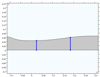
In the Settings window for Streamline, click Replace Expression in the upper-right corner of the Expression section. From the menu, choose Component 1 (comp1)>High Mach Number Flow, Spalart-Allmaras (Fluid Flow)>Velocity and pressure>u,v - Velocity field.
3
4
Locate the Streamline Positioning section. In the Number text field, type 9.
Contour 1
1
Right-click Mach Number (hmnf) 1 and choose Contour.
2
In the Settings window for Contour, click Replace Expression in the upper-right corner of the Expression section. From the menu, choose Component 1 (comp1)>High Mach Number Flow, Spalart-Allmaras (Fluid Flow)>Velocity and pressure>Velocity field - m/s>u - Velocity field, x component.
3
Locate the Levels section. From the Entry method list, choose Levels.
4
Locate the Coloring and Style section. From the Coloring list, choose Uniform.
5
Clear the Color legend check box.
6
In the Mach Number (hmnf) 1 toolbar, click  Plot.
Select all the new 2D plots, right-click and select Group.
Strong Shock
1
In the Model Builder window, under Results click Group 2.
2
In the Settings window for Group, type Strong Shock in the Label text field.
Create cut line datasets to plot results at two downstream positions in the diverging part of the nozzle.
Cut Line 2D 1
1
In the Model Builder window, expand the Results>Datasets node.
2
Right-click Datasets and choose Cut Line 2D.
3
In the Settings window for Cut Line 2D, locate the Data section.
4
From the Dataset list, choose Study 2/Solution 5 (sol5).
5
Locate the Line Data section. In row Point 1, set x to 4.611*h_th.
6
In row Point 2, set x to 4.611*h_th and y to 2*h_th.
7
The position of the cut line is indicated with a red line.
Cut Line 2D 2
1
In the Results toolbar, click  Cut Line 2D.
2
In the Settings window for Cut Line 2D, locate the Data section.
3
From the Dataset list, choose Study 2/Solution 5 (sol5).
4
Locate the Line Data section. In row Point 1, set x to 6.340*h_th.
5
In row Point 2, set x to 6.340*h_th and y to 2*h_th.
6
The following steps reproduce the normalized static pressure plots in Figure 4.
1D Plot Group 13
1
In the Results toolbar, click  1D Plot Group.
2
In the Settings window for 1D Plot Group, locate the Data section.
3
From the Parameter selection (Rein) list, choose Last.
Line Graph 1
1
Right-click 1D Plot Group 13 and choose Line Graph.
2
3
In the Settings window for Line Graph, locate the y-Axis Data section.
4
In the Expression text field, type p/pin_tot.
5
Click Replace Expression in the upper-right corner of the x-Axis Data section. From the menu, choose Component 1 (comp1)>Geometry>Coordinate>x - x-coordinate.
Line Graph 2
1
Right-click Line Graph 1 and choose Duplicate.
2
In the Settings window for Line Graph, locate the y-Axis Data section.
3
In the Expression text field, type ptop_weak(x/h_th).
4
Click to expand the Coloring and Style section. Find the Line style subsection. From the Line list, choose None.
5
From the Color list, choose Black.
6
Find the Line markers subsection. From the Marker list, choose Diamond.
7
In the Number text field, type 30.
1D Plot Group 13
1
In the Model Builder window, click 1D Plot Group 13.
2
In the Settings window for 1D Plot Group, click to expand the Title section.
3
From the Title type list, choose Manual.
4
In the Title text area, type Weak shock.
5
Locate the Axis section. Select the Manual axis limits check box.
6
In the x minimum text field, type -0.2.
7
In the x maximum text field, type 0.4.
8
In the y minimum text field, type 0.25.
9
In the y maximum text field, type 1.
10
Locate the Grid section. Select the Manual spacing check box.
11
In the x spacing text field, type 0.05.
12
In the y spacing text field, type 0.1.
13
In the 1D Plot Group 13 toolbar, click  Plot.
Compare the result with that in the left panel of Figure 4.
To reproduce the plot in the right panel, use the plot you just created as the starting point.
1D Plot Group 14
1
Right-click Results>1D Plot Group 13 and choose Duplicate.
2
In the Settings window for 1D Plot Group, locate the Data section.
3
From the Dataset list, choose Study 2/Solution 5 (sol5).
4
Locate the Title section. In the Title text area, type Strong shock.
Line Graph 2
1
In the Model Builder window, expand the 1D Plot Group 14 node, then click Line Graph 2.
2
In the Settings window for Line Graph, locate the y-Axis Data section.
3
In the Expression text field, type ptop_strong(x/h_th).
4
In the 1D Plot Group 14 toolbar, click  Plot.
1D Plot Group 14
1
In the Model Builder window, click 1D Plot Group 14.
2
Compare with the right panel of Figure 4.
Similarly, reproduce the x-velocity plots in Figure 5.
1D Plot Group 15
1
In the Home toolbar, click  Add Plot Group and choose 1D Plot Group.
2
In the Settings window for 1D Plot Group, locate the Data section.
3
From the Dataset list, choose Cut Line 2D 1.
Line Graph 1
1
Right-click 1D Plot Group 15 and choose Line Graph.
2
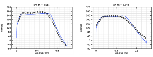
In the Settings window for Line Graph, click Replace Expression in the upper-right corner of the y-Axis Data section. From the menu, choose Component 1 (comp1)>High Mach Number Flow, Spalart-Allmaras (Fluid Flow)>Velocity and pressure>Velocity field - m/s>u - Velocity field, x component.
3
Locate the x-Axis Data section. From the Parameter list, choose Expression.
4
In the Expression text field, type y/0.0617.
Line Graph 2
1
In the Model Builder window, right-click 1D Plot Group 15 and choose Line Graph.
2
In the Settings window for Line Graph, locate the y-Axis Data section.
3
In the Expression text field, type u_at4611(y/0.0617).
4
Locate the x-Axis Data section. From the Parameter list, choose Expression.
5
In the Expression text field, type y/0.0617.
6
Locate the Coloring and Style section. Find the Line style subsection. From the Line list, choose None.
7
From the Color list, choose Black.
8
Find the Line markers subsection. From the Marker list, choose Diamond.
9
In the Number text field, type 30.
1D Plot Group 15
1
In the Model Builder window, click 1D Plot Group 15.
2
In the Settings window for 1D Plot Group, locate the Title section.
3
From the Title type list, choose Manual.
4
In the Title text area, type x/h_th = 4.611.
5
Locate the Plot Settings section. Select the y-axis label check box.
6
7
Locate the Axis section. Select the Manual axis limits check box.
8
In the x minimum text field, type -0.1.
9
In the x maximum text field, type 1.1.
10
In the y minimum text field, type -80.
11
In the y maximum text field, type 320.
12
Locate the Grid section. Select the Manual spacing check box.
13
In the x spacing text field, type 0.05.
14
In the y spacing text field, type 20.
15
In the 1D Plot Group 15 toolbar, click  Plot.
1D Plot Group 16
1
Right-click Results>1D Plot Group 15 and choose Duplicate.
2
In the Settings window for 1D Plot Group, locate the Data section.
3
From the Dataset list, choose Cut Line 2D 2.
4
Locate the Title section. In the Title text area, type x/h_th = 6.340.
Line Graph 1
1
In the Model Builder window, expand the 1D Plot Group 16 node, then click Line Graph 1.
2
In the Settings window for Line Graph, locate the x-Axis Data section.
3
In the Expression text field, type y/0.066.
Line Graph 2
1
In the Model Builder window, click Line Graph 2.
2
In the Settings window for Line Graph, locate the y-Axis Data section.
3
In the Expression text field, type u_at6340(y/0.066).
4
Locate the x-Axis Data section. In the Expression text field, type y/0.066.
5
In the 1D Plot Group 16 toolbar, click  Plot.