PDF

Operational Amplifier with Capacitive Load
Introduction
An Operational Amplifier (op-amp) is a differential voltage amplifier with a wide range of applications in analog electronics. This example shows how to model an operational amplifier connected to a feedback loop and a capacitive load and calculate the transient step response of the entire system. The basic op-amp model used here is implemented as an equivalent linear subcircuit in the Electrical Circuit interface in COMSOL Multiphysics. The latter is partially based on the SPICE format originally developed at Berkeley University (Ref. 1).
Model Definition
The op-amp subcircuit is described by the following lines in a SPICE netlist:
.SUBCKT OPAMP p n out gnd
RIN p n 100000.0
EGAIN 1 gnd p n 100000.0
RP 1 2 1591549.4309189531
CP 2 gnd 1.0E-9
EBUFFER 3 gnd 2 gnd 1.0
ROUT 3 out 100.0
.ENDS OPAMP
The different stages are:
The op-amp subcrcuit instance is then inserted into the main circuit:
VIN 1 0 DC 0.5
XOPAMP 1 2 3 0 OPAMP
R1 2 0 470.0
R2 2 3 4700.0
CLOAD 3 0 1.0E-8
Here the voltage source is indicated as being constant at 0.5V whereas in the model a voltage step of 0.5V is applied at t=0. A resistive feedback loop is provided through the resistors R1 and R2 and the amplifier output is terminated to ground via a capacitive load CLOAD.
Results and Discussion
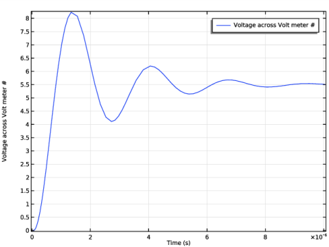
The model is simulated for 10μs with data output every 0.05μs. The internal dynamics of the op-amp interacts with the feedback network causing ringing in the output signal.
Figure 1: The output voltage of the op-amp as a function of time.
Reference
1. The SPICE home page, http://bwrc.eecs.berkeley.edu/Classes/IcBook/SPICE.
Application Library path: ACDC_Module/Tutorials/opamp_capacitive_load
Modeling Instructions
From the File menu, choose New.
New
In the New window, click  Model Wizard.
Model Wizard
1
In the Model Wizard window, click  0D.
2
In the Select Physics tree, select AC/DC>Electrical Circuit (cir).
3
Click Add.
4
Click  Study.
5
In the Select Study tree, select General Studies>Time Dependent.
6
Global Definitions
Start by defining the parameters to be used in the model.
Parameters 1
1
In the Model Builder window, under Global Definitions click Parameters 1.
2
In the Settings window for Parameters, locate the Parameters section.
3
Definitions
Add a step function and a variable defining the voltage step used to drive the model.
Step 1 (step1)
In the Home toolbar, click  Functions and choose Local>Step.
Variables 1
1
In the Home toolbar, click  Variables and choose Local Variables.
2
In the Settings window for Variables, locate the Variables section.
3
Electrical Circuit (cir)
Now, define the circuit. Start by defining the subcircuit for the op-amp.
OPAMP
1
In the Model Builder window, under Component 1 (comp1) right-click Electrical Circuit (cir) and choose Subcircuit Definition.
2
In the Settings window for Subcircuit Definition, type OPAMP in the Label text field.
3
Locate the Node Connections section. Click  Add.
4
5
Resistor RIN
1
In the Electrical Circuit toolbar, click  Resistor.
2
In the Settings window for Resistor, type Resistor RIN in the Label text field.
3
In the Name text field, type RIN.
4
Locate the Node Connections section. In the table, enter the following settings:
5
Locate the Device Parameters section. In the R text field, type OPAMP_RIN.
Voltage-Controlled Voltage Source EGAIN
1
In the Electrical Circuit toolbar, click  Voltage-Controlled Voltage Source.
2
In the Settings window for Voltage-Controlled Voltage Source, type Voltage-Controlled Voltage Source EGAIN in the Label text field.
3
In the Name text field, type EGAIN.
4
Locate the Node Connections section. In the table, enter the following settings:
5
Locate the Device Parameters section. In the Gain text field, type OPAMP_GAIN.
Resistor RP
1
In the Electrical Circuit toolbar, click  Resistor.
2
In the Settings window for Resistor, type Resistor RP in the Label text field.
3
In the Name text field, type RP.
4
Locate the Node Connections section. In the table, enter the following settings:
5
Locate the Device Parameters section. In the R text field, type 1/(2*pi*OPAMP_P*1[nF]).
Capacitor CP
1
In the Electrical Circuit toolbar, click  Capacitor.
2
In the Settings window for Capacitor, type Capacitor CP in the Label text field.
3
In the Name text field, type CP.
4
Locate the Node Connections section. In the table, enter the following settings:
5
Locate the Device Parameters section. In the C text field, type 1[nF].
Voltage-Controlled Voltage Source EBUFFER
1
In the Electrical Circuit toolbar, click  Voltage-Controlled Voltage Source.
2
In the Settings window for Voltage-Controlled Voltage Source, type Voltage-Controlled Voltage Source EBUFFER in the Label text field.
3
In the Name text field, type EBUFFER.
4
Locate the Node Connections section. In the table, enter the following settings:
Resistor ROUT
1
In the Electrical Circuit toolbar, click  Resistor.
2
In the Settings window for Resistor, type Resistor ROUT in the Label text field.
3
In the Name text field, type ROUT.
4
Locate the Node Connections section. In the table, enter the following settings:
5
Locate the Device Parameters section. In the R text field, type OPAMP_ROUT.
Voltage Source VIN
Proceed to add the main circuit, start by adding the voltage source.
1
In the Electrical Circuit toolbar, click  Voltage Source.
2
In the Settings window for Voltage Source, type Voltage Source VIN in the Label text field.
3
In the Name text field, type VIN.
4
Locate the Node Connections section. In the table, enter the following settings:
5
Locate the Device Parameters section. In the vsrc text field, type VIN.
Subcircuit Instance XOPAMP
Add the subcircuit instance for the opamp.
1
In the Electrical Circuit toolbar, click  Subcircuit Instance.
2
In the Settings window for Subcircuit Instance, type Subcircuit Instance XOPAMP in the Label text field.
3
In the Name text field, type XOPAMP.
4
Locate the Node Connections section. From the Name of subcircuit link list, choose OPAMP (sub1).
5
Resistor 1 (R1)
1
In the Electrical Circuit toolbar, click  Resistor.
2
In the Settings window for Resistor, locate the Node Connections section.
3
4
Locate the Device Parameters section. In the R text field, type R1.
Resistor 2 (R2)
1
In the Electrical Circuit toolbar, click  Resistor.
2
In the Settings window for Resistor, locate the Node Connections section.
3
4
Locate the Device Parameters section. In the R text field, type R2.
Capacitor CLOAD
1
In the Electrical Circuit toolbar, click  Capacitor.
2
In the Settings window for Capacitor, type Capacitor CLOAD in the Label text field.
3
In the Name text field, type CLOAD.
4
Locate the Node Connections section. In the table, enter the following settings:
5
Locate the Device Parameters section. In the C text field, type CLOAD.
Volt Meter 1 (vm1)
In order to see the output voltage, a voltmeter is added.
1
In the Electrical Circuit toolbar, click  Volt Meter.
2
In the Settings window for Volt Meter, locate the Node Connections section.
3
Study 1
Step 1: Time Dependent
1
In the Model Builder window, under Study 1 click Step 1: Time Dependent.
2
In the Settings window for Time Dependent, locate the Study Settings section.
3
Click  Range.
4
In the Range dialog box, type 0.05[us] in the Step text field.
5
In the Stop text field, type 10[us].
6
Click Replace.
7
In the Home toolbar, click  Compute.
Results
Probe Plot Group 1
The output voltage appears as a probe plot.
Root
Finally add a model thumbnail image.
1
In the Model Builder window, click the root node.
2
In the root node’s Settings window, locate the Presentation section.
3
Find the Thumbnail subsection. Click Set from Graphics Window.