PDF

Inductance Matrix Calculation of PCB Coils
Introduction
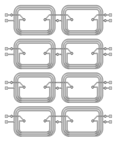
PCB (printed-circuit board) coils are widely used in a variety of industrial applications such as micromotor and microelectronic devices. For an array of PCB coils, it is generally of interest to know the inductive coupling represented by the inductance matrix. This model demonstrates how to use the Magnetic Fields, Currents Only interface to compute the inductance matrix of an array of coils in a multilayer PCB, as shown in Figure 1.
Figure 1: The geometry of PCB coils.
Model Definition
The geometry of the coils is usually ‘open’; the modeling of a closed current loop is not of interest and is also not necessary. The Magnetic Fields, Currents Only interface can model such nondivergence-free currents. For more details, see Theory for the Magnetic Fields, Currents Only Interface in the AC/DC Module User’s Guide.
The PCB coils are modeled by the Conductor feature, which can be used to easily set up the current sources. The model is solved with a Stationary Source Sweep with Initialization study, which is dedicated to computing the lumped inductance matrix.
Results and Discussion
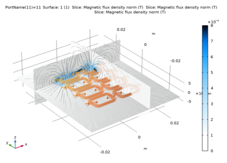
Figure 2 shows the distribution of the magnetic flux density norm around the PCB coils when the 11th conductor is activated. Figure 3 illustrates the inductance matrix of the PCB coils.
Figure 2: The distribution of the magnetic flux density norm around PCB coils.
Figure 3: Visualization of the inductance matrix of PCB coils.
Application Library path: ACDC_Module/Inductive_Devices_and_Coils/inductance_matrix_pcb_coils
Modeling Instructions
From the File menu, choose New.
New
In the New window, click  Model Wizard.
Model Wizard
1
In the Model Wizard window, click  3D.
2
In the Select Physics tree, select AC/DC>Electromagnetic Fields>Vector Formulations>Magnetic Fields, Currents Only (mfco).
3
Click Add.
4
Click  Study.
5
In the Select Study tree, select Preset Studies for Selected Physics Interfaces>Stationary Source Sweep with Initialization.
6
Geometry 1
1
In the Model Builder window, under Component 1 (comp1) click Geometry 1.
2
In the Settings window for Geometry, locate the Advanced section.
3
From the Geometry representation list, choose CAD kernel.
Import 1 (imp1)
1
In the Home toolbar, click  Import.
2
In the Settings window for Import, locate the Import section.
3
From the Source list, choose COMSOL Multiphysics file.
4
In the Filename text field, type inductance_matrix_pcb_coils.mphbin.
5
Click Import.
6
Click the  Transparency button in the Graphics toolbar.
Explicit Selection 1 (sel1)
1
In the Geometry toolbar, click  Selections and choose Explicit Selection.
2
On the object imp1, select Domains 4, 5, 8–15, 26–31, and 34–54 only.
Complement Selection 1 (comsel1)
1
In the Geometry toolbar, click  Selections and choose Complement Selection.
2
In the Settings window for Complement Selection, locate the Input Entities section.
3
4
In the Add dialog box, select Explicit Selection 1 in the Selections to invert list.
5
Delete Entities 1 (del1)
1
In the Model Builder window, right-click Geometry 1 and choose Delete Entities.
2
On the object imp1, select Domains 1–3, 6, 7, 16–25, 32, and 33 only.
3
In the Settings window for Delete Entities, locate the Entities or Objects to Delete section.
4
From the Geometric entity level list, choose Domain.
5
From the Selection list, choose Complement Selection 1.
Array 1 (arr1)
1
In the Geometry toolbar, click  Transforms and choose Array.
2
3
In the Settings window for Array, locate the Size section.
4
In the x size text field, type 2.
5
Locate the Displacement section. In the x text field, type 16.25[mm].
Block 1 (blk1)
1
In the Geometry toolbar, click  Block.
2
In the Settings window for Block, locate the Size and Shape section.
3
In the Width text field, type 0.01-0.00625+0.0002.
4
In the Depth text field, type 0.001375.
5
In the Height text field, type 0.01.
6
Locate the Position section. In the x text field, type 0.00625-0.0001.
7
In the y text field, type 0.001375/2.
8
In the z text field, type -0.005.
Block 2 (blk2)
1
In the Geometry toolbar, click  Block.
2
In the Settings window for Block, locate the Size and Shape section.
3
In the Width text field, type 0.0025.
4
In the Depth text field, type 0.001375.
5
In the Height text field, type 0.01.
6
Locate the Position section. In the x text field, type 0.0075.
7
In the y text field, type -0.001375/2.
8
In the z text field, type -0.005.
Difference 1 (dif1)
1
In the Geometry toolbar, click  Booleans and Partitions and choose Difference.
2
Select the objects arr1(1,1,1) and arr1(2,1,1) only.
3
In the Settings window for Difference, locate the Difference section.
4
Find the Objects to subtract subsection. Select the  Activate Selection toggle button.
5
Select the objects blk1 and blk2 only.
Split 1 (spl1)
1
In the Geometry toolbar, click  Conversions and choose Split.
2
Move 1 (mov1)
1
In the Geometry toolbar, click  Transforms and choose Move.
2
Select the objects spl1(15), spl1(16), spl1(17), spl1(18), spl1(19), spl1(20), spl1(21), spl1(22), spl1(23), spl1(24), spl1(25), spl1(26), spl1(27), spl1(28), spl1(29), spl1(30), spl1(31), spl1(32), spl1(33), spl1(34), spl1(35), spl1(50), spl1(51), spl1(52), spl1(53), spl1(54), spl1(55), spl1(56), spl1(57), and spl1(59) only.
3
In the Settings window for Move, locate the Displacement section.
4
In the x text field, type -0.0025.
5
Click  Build Selected.
Extrude 1 (ext1)
1
In the Geometry toolbar, click  Extrude.
2
On the object mov1(26), select Boundary 1 only.
3
In the Settings window for Extrude, locate the Distances section.
4
Union 1 (uni1)
1
In the Geometry toolbar, click  Booleans and Partitions and choose Union.
2
Select the objects spl1(1), spl1(10), spl1(11), spl1(12), spl1(13), spl1(14), spl1(2), spl1(3), spl1(4), spl1(5), spl1(6), spl1(60), spl1(7), spl1(8), and spl1(9) only.
3
In the Settings window for Union, locate the Selections of Resulting Entities section.
4
Select the Resulting objects selection check box.
Union 2 (uni2)
1
In the Geometry toolbar, click  Booleans and Partitions and choose Union.
2
Select the objects ext1, mov1(22), mov1(23), mov1(25), mov1(27), mov1(28), mov1(29), spl1(36), spl1(37), spl1(38), spl1(39), spl1(40), spl1(41), spl1(42), spl1(43), spl1(44), spl1(45), spl1(46), spl1(47), spl1(48), spl1(49), and spl1(58) only.
3
In the Settings window for Union, locate the Selections of Resulting Entities section.
4
Select the Resulting objects selection check box.
Union 3 (uni3)
1
In the Geometry toolbar, click  Booleans and Partitions and choose Union.
2
Select the objects mov1(1), mov1(10), mov1(11), mov1(12), mov1(13), mov1(14), mov1(15), mov1(16), mov1(17), mov1(18), mov1(19), mov1(2), mov1(20), mov1(21), mov1(24), mov1(3), mov1(30), mov1(4), mov1(5), mov1(6), mov1(7), mov1(8), and mov1(9) only.
3
In the Settings window for Union, locate the Selections of Resulting Entities section.
4
Select the Resulting objects selection check box.
Array 2 (arr2)
1
In the Geometry toolbar, click  Transforms and choose Array.
2
Click in the Graphics window and then press Ctrl+A to select all objects.
3
In the Settings window for Array, locate the Size section.
4
In the y size text field, type 4.
5
Locate the Displacement section. In the y text field, type 9[mm].
6
Click  Build Selected.
Coils
1
In the Geometry toolbar, click  Transforms and choose Move.
2
Click in the Graphics window and then press Ctrl+A to select all objects.
3
In the Settings window for Move, locate the Displacement section.
4
In the x text field, type -(0.02225-0.0085)/2.
5
In the y text field, type -(0.031-0.004)/2.
6
In the z text field, type -(6.500803969E-4-7.508789687E-5)/2.
7
Locate the Selections of Resulting Entities section. Select the Resulting objects selection check box.
8
From the Show in physics list, choose All levels.
9
In the Label text field, type Coils.
Block 3 (blk3)
1
In the Geometry toolbar, click  Block.
2
In the Settings window for Block, locate the Size and Shape section.
3
In the Width text field, type 5[cm].
4
In the Depth text field, type 6[cm].
5
In the Height text field, type 2[cm].
6
Locate the Position section. From the Base list, choose Center.
Work Plane 1 (wp1)
1
In the Geometry toolbar, click  Work Plane.
2
In the Settings window for Work Plane, locate the Plane Definition section.
3
In the z-coordinate text field, type -2[mm].
Partition Objects 1 (par1)
1
In the Geometry toolbar, click  Booleans and Partitions and choose Partition Objects.
2
3
In the Settings window for Partition Objects, locate the Partition Objects section.
4
From the Partition with list, choose Work plane.
Work Plane 2 (wp2)
1
In the Geometry toolbar, click  Work Plane.
2
In the Settings window for Work Plane, locate the Plane Definition section.
3
From the Plane list, choose yz-plane.
4
In the x-coordinate text field, type 7[mm].
Partition Objects 2 (par2)
1
In the Geometry toolbar, click  Booleans and Partitions and choose Partition Objects.
2
3
In the Settings window for Partition Objects, locate the Partition Objects section.
4
From the Partition with list, choose Work plane.
Work Plane 3 (wp3)
1
In the Geometry toolbar, click  Work Plane.
2
In the Settings window for Work Plane, locate the Plane Definition section.
3
From the Plane list, choose zx-plane.
4
In the y-coordinate text field, type 14.25[mm].
Partition Objects 3 (par3)
1
In the Geometry toolbar, click  Booleans and Partitions and choose Partition Objects.
2
3
In the Settings window for Partition Objects, locate the Partition Objects section.
4
From the Partition with list, choose Work plane.
Form Union (fin)
1
In the Geometry toolbar, click  Build All.
2
Click the  Go to Default View button in the Graphics toolbar.
Definitions
The geometry is now complete. Next, define coil selections for the physics interface to use.
Box 1
1
In the Model Builder window, expand the Component 1 (comp1)>Definitions node.
2
Right-click Component 1 (comp1)>Definitions>Selections and choose Box.
3
In the Settings window for Box, locate the Input Entities section.
4
From the Entities list, choose From selections.
5
Under Selections, click  Add.
6
In the Add dialog box, select Union 1 in the Selections list.
7
8
In the Settings window for Box, locate the Box Limits section.
9
In the x minimum text field, type -10[cm].
10
In the x maximum text field, type 10[cm].
11
In the y maximum text field, type -9[mm].
12
In the z minimum text field, type -1[cm].
13
In the z maximum text field, type 1[cm].
14
Locate the Output Entities section. From the Include entity if list, choose Entity inside box.
Box 2
1
In the Definitions toolbar, click  Box.
2
In the Settings window for Box, locate the Input Entities section.
3
From the Entities list, choose From selections.
4
Under Selections, click  Add.
5
In the Add dialog box, select Union 2 in the Selections list.
6
7
In the Settings window for Box, locate the Box Limits section.
8
In the x minimum text field, type -10[cm].
9
In the x maximum text field, type 10[cm].
10
In the y maximum text field, type -9[mm].
11
In the z minimum text field, type -1[cm].
12
In the z maximum text field, type 1[cm].
13
Locate the Output Entities section. From the Include entity if list, choose Entity inside box.
Box 3
1
In the Definitions toolbar, click  Box.
2
In the Settings window for Box, locate the Input Entities section.
3
From the Entities list, choose From selections.
4
Under Selections, click  Add.
5
In the Add dialog box, select Union 3 in the Selections list.
6
7
In the Settings window for Box, locate the Box Limits section.
8
In the x minimum text field, type -10[cm].
9
In the x maximum text field, type 10[cm].
10
In the y maximum text field, type -9[mm].
11
In the z minimum text field, type -1[cm].
12
In the z maximum text field, type 1[cm].
13
Locate the Output Entities section. From the Include entity if list, choose Entity inside box.
Box 4
1
In the Definitions toolbar, click  Box.
2
In the Settings window for Box, locate the Input Entities section.
3
From the Entities list, choose From selections.
4
Under Selections, click  Add.
5
In the Add dialog box, select Union 1 in the Selections list.
6
7
In the Settings window for Box, locate the Box Limits section.
8
In the x minimum text field, type -10[cm].
9
In the x maximum text field, type 10[cm].
10
In the y minimum text field, type -9[mm].
11
In the y maximum text field, type 0.
12
In the z minimum text field, type -1[cm].
13
In the z maximum text field, type 1[cm].
14
Locate the Output Entities section. From the Include entity if list, choose Entity inside box.
Box 5
1
In the Definitions toolbar, click  Box.
2
In the Settings window for Box, locate the Input Entities section.
3
From the Entities list, choose From selections.
4
Under Selections, click  Add.
5
In the Add dialog box, select Union 2 in the Selections list.
6
7
In the Settings window for Box, locate the Box Limits section.
8
In the x minimum text field, type -10[cm].
9
In the x maximum text field, type 10[cm].
10
In the y minimum text field, type -9[mm].
11
In the y maximum text field, type 0.
12
In the z minimum text field, type -1[cm].
13
In the z maximum text field, type 1[cm].
14
Locate the Output Entities section. From the Include entity if list, choose Entity inside box.
Box 6
1
In the Definitions toolbar, click  Box.
2
In the Settings window for Box, locate the Input Entities section.
3
From the Entities list, choose From selections.
4
Under Selections, click  Add.
5
In the Add dialog box, select Union 3 in the Selections list.
6
7
In the Settings window for Box, locate the Box Limits section.
8
In the x minimum text field, type -10[cm].
9
In the x maximum text field, type 10[cm].
10
In the y minimum text field, type -9[mm].
11
In the y maximum text field, type 0.
12
In the z minimum text field, type -1[cm].
13
In the z maximum text field, type 1[cm].
14
Locate the Output Entities section. From the Include entity if list, choose Entity inside box.
Box 7
In the Definitions toolbar, click  Box.
Box 8
In the Definitions toolbar, click  Box.
Box 9
In the Definitions toolbar, click  Box.
Box 7
1
In the Model Builder window, click Box 7.
2
In the Settings window for Box, locate the Input Entities section.
3
From the Entities list, choose From selections.
4
Under Selections, click  Add.
5
In the Add dialog box, select Union 1 in the Selections list.
6
7
In the Settings window for Box, locate the Box Limits section.
8
In the x minimum text field, type -10[cm].
9
In the x maximum text field, type 10[cm].
10
In the y minimum text field, type 0.
11
In the y maximum text field, type 9[mm].
12
In the z minimum text field, type -1[cm].
13
In the z maximum text field, type 1[cm].
14
Locate the Output Entities section. From the Include entity if list, choose Entity inside box.
Box 8
1
In the Model Builder window, click Box 8.
2
In the Settings window for Box, locate the Input Entities section.
3
From the Entities list, choose From selections.
4
Under Selections, click  Add.
5
In the Add dialog box, select Union 2 in the Selections list.
6
7
In the Settings window for Box, locate the Box Limits section.
8
In the x minimum text field, type -10[cm].
9
In the x maximum text field, type 10[cm].
10
In the y minimum text field, type 0.
11
In the y maximum text field, type 9[mm].
12
In the z minimum text field, type -1[cm].
13
In the z maximum text field, type 1[cm].
14
Locate the Output Entities section. From the Include entity if list, choose Entity inside box.
Box 9
1
In the Model Builder window, click Box 9.
2
In the Settings window for Box, locate the Input Entities section.
3
From the Entities list, choose From selections.
4
Under Selections, click  Add.
5
In the Add dialog box, select Union 3 in the Selections list.
6
7
In the Settings window for Box, locate the Box Limits section.
8
In the x minimum text field, type -10[cm].
9
In the x maximum text field, type 10[cm].
10
In the y minimum text field, type 0.
11
In the y maximum text field, type 9[mm].
12
In the z minimum text field, type -1[cm].
13
In the z maximum text field, type 1[cm].
14
Locate the Output Entities section. From the Include entity if list, choose Entity inside box.
Box 10
In the Definitions toolbar, click  Box.
Box 11
In the Definitions toolbar, click  Box.
Box 12
In the Definitions toolbar, click  Box.
Box 10
1
In the Model Builder window, click Box 10.
2
In the Settings window for Box, locate the Input Entities section.
3
From the Entities list, choose From selections.
4
Under Selections, click  Add.
5
In the Add dialog box, select Union 1 in the Selections list.
6
7
In the Settings window for Box, locate the Box Limits section.
8
In the x minimum text field, type -10[cm].
9
In the x maximum text field, type 10[cm].
10
In the y minimum text field, type 9[mm].
11
In the z minimum text field, type -1[cm].
12
In the z maximum text field, type 1[cm].
13
Locate the Output Entities section. From the Include entity if list, choose Entity inside box.
Box 11
1
In the Model Builder window, click Box 11.
2
In the Settings window for Box, locate the Input Entities section.
3
From the Entities list, choose From selections.
4
Under Selections, click  Add.
5
In the Add dialog box, select Union 2 in the Selections list.
6
7
In the Settings window for Box, locate the Box Limits section.
8
In the x minimum text field, type -10[cm].
9
In the x maximum text field, type 10[cm].
10
In the y minimum text field, type 9[mm].
11
In the z minimum text field, type -1[cm].
12
In the z maximum text field, type 1[cm].
Box 12
1
In the Model Builder window, click Box 12.
2
In the Settings window for Box, locate the Input Entities section.
3
From the Entities list, choose From selections.
4
Under Selections, click  Add.
5
In the Add dialog box, select Union 3 in the Selections list.
6
7
In the Settings window for Box, locate the Box Limits section.
8
In the x minimum text field, type -10[cm].
9
In the x maximum text field, type 10[cm].
10
In the y minimum text field, type 9[mm].
11
In the z minimum text field, type -1[cm].
12
In the z maximum text field, type 1[cm].
13
Locate the Output Entities section. From the Include entity if list, choose Entity inside box.
Magnetic Fields, Currents Only (mfco)
Conductor 1
1
In the Model Builder window, under Component 1 (comp1) right-click Magnetic Fields, Currents Only (mfco) and choose Conductor.
2
In the Settings window for Conductor, locate the Domain Selection section.
3
From the Selection list, choose Box 1.
Ground 1
In the Physics toolbar, click  Attributes and choose Ground.
Terminal 1
1
In the Model Builder window, click Terminal 1.
2
Ground 1
1
In the Model Builder window, click Ground 1.
2
Conductor 2
1
In the Physics toolbar, click  Domains and choose Conductor.
2
In the Settings window for Conductor, locate the Domain Selection section.
3
From the Selection list, choose Box 2.
Terminal 1
1
In the Model Builder window, expand the Conductor 2 node, then click Terminal 1.
2
Conductor 3
1
In the Physics toolbar, click  Domains and choose Conductor.
2
In the Settings window for Conductor, locate the Domain Selection section.
3
From the Selection list, choose Box 3.
Ground 1
In the Physics toolbar, click  Attributes and choose Ground.
Terminal 1
1
In the Model Builder window, click Terminal 1.
2
Ground 1
1
In the Model Builder window, click Ground 1.
2
Conductor 4
1
In the Physics toolbar, click  Domains and choose Conductor.
2
In the Settings window for Conductor, locate the Domain Selection section.
3
From the Selection list, choose Box 4.
Ground 1
In the Physics toolbar, click  Attributes and choose Ground.
Terminal 1
1
In the Model Builder window, click Terminal 1.
2
Ground 1
1
In the Model Builder window, click Ground 1.
2
Conductor 5
1
In the Physics toolbar, click  Domains and choose Conductor.
2
In the Settings window for Conductor, locate the Domain Selection section.
3
From the Selection list, choose Box 5.
Terminal 1
1
In the Model Builder window, expand the Conductor 5 node, then click Terminal 1.
2
Conductor 6
1
In the Physics toolbar, click  Domains and choose Conductor.
2
In the Settings window for Conductor, locate the Domain Selection section.
3
From the Selection list, choose Box 6.
Ground 1
In the Physics toolbar, click  Attributes and choose Ground.
Terminal 1
1
In the Model Builder window, click Terminal 1.
2
Ground 1
1
In the Model Builder window, click Ground 1.
2
Conductor 7
1
In the Physics toolbar, click  Domains and choose Conductor.
2
In the Settings window for Conductor, locate the Domain Selection section.
3
From the Selection list, choose Box 7.
Ground 1
In the Physics toolbar, click  Attributes and choose Ground.
Terminal 1
1
In the Model Builder window, click Terminal 1.
2
Ground 1
1
In the Model Builder window, click Ground 1.
2
Conductor 8
1
In the Physics toolbar, click  Domains and choose Conductor.
2
In the Settings window for Conductor, locate the Domain Selection section.
3
From the Selection list, choose Box 8.
Terminal 1
1
In the Model Builder window, expand the Conductor 8 node, then click Terminal 1.
2
Conductor 9
1
In the Physics toolbar, click  Domains and choose Conductor.
2
In the Settings window for Conductor, locate the Domain Selection section.
3
From the Selection list, choose Box 9.
Ground 1
In the Physics toolbar, click  Attributes and choose Ground.
Terminal 1
1
In the Model Builder window, click Terminal 1.
2
Ground 1
1
In the Model Builder window, click Ground 1.
2
Conductor 10
1
In the Physics toolbar, click  Domains and choose Conductor.
2
In the Settings window for Conductor, locate the Domain Selection section.
3
From the Selection list, choose Box 10.
Ground 1
In the Physics toolbar, click  Attributes and choose Ground.
Terminal 1
1
In the Model Builder window, click Terminal 1.
2
Ground 1
1
In the Model Builder window, click Ground 1.
2
Conductor 11
1
In the Physics toolbar, click  Domains and choose Conductor.
2
In the Settings window for Conductor, locate the Domain Selection section.
3
From the Selection list, choose Box 11.
Terminal 1
1
In the Model Builder window, expand the Conductor 11 node, then click Terminal 1.
2
Conductor 12
1
In the Physics toolbar, click  Domains and choose Conductor.
2
In the Settings window for Conductor, locate the Domain Selection section.
3
From the Selection list, choose Box 12.
Ground 1
In the Physics toolbar, click  Attributes and choose Ground.
Terminal 1
1
In the Model Builder window, click Terminal 1.
2
Ground 1
1
In the Model Builder window, click Ground 1.
2
Definitions
Hide for Physics 1
1
In the Model Builder window, right-click View 1 and choose Hide for Physics.
2
In the Settings window for Hide for Physics, locate the Geometric Entity Selection section.
3
From the Geometric entity level list, choose Boundary.
4
Mesh 1
1
In the Model Builder window, under Component 1 (comp1) click Mesh 1.
2
In the Settings window for Mesh, locate the Physics-Controlled Mesh section.
3
From the Element size list, choose Fine.
4
Click the  Go to Default View button in the Graphics toolbar.
5
Click the  Transparency button in the Graphics toolbar.
6
Click  Build All.
Materials
Material 1 (mat1)
1
In the Model Builder window, under Component 1 (comp1) right-click Materials and choose Blank Material.
2
In the Settings window for Material, locate the Geometric Entity Selection section.
3
From the Selection list, choose Coils.
4
Locate the Material Contents section. In the table, enter the following settings:
Study 1
In the Home toolbar, click  Compute.
Results
Cut Plane 1
1
In the Model Builder window, expand the Results>Datasets node, then click Cut Plane 1.
2
In the Settings window for Cut Plane, locate the Plane Data section.
3
In the z-coordinate text field, type -2[mm].
Cut Plane 2
1
In the Model Builder window, click Cut Plane 2.
2
In the Settings window for Cut Plane, locate the Plane Data section.
3
In the x-coordinate text field, type 7[mm].
Cut Plane 3
1
In the Model Builder window, click Cut Plane 3.
2
In the Settings window for Cut Plane, locate the Plane Data section.
3
In the y-coordinate text field, type 14.25[mm].
Multislice 1
1
In the Model Builder window, expand the Magnetic Flux Density Norm (mfco) node.
2
Right-click Multislice 1 and choose Delete.
Surface 1
1
In the Model Builder window, right-click Magnetic Flux Density Norm (mfco) and choose Surface.
2
In the Settings window for Surface, locate the Expression section.
3
In the Expression text field, type 1.
Selection 1
1
Right-click Surface 1 and choose Selection.
2
In the Settings window for Selection, locate the Selection section.
3
From the Selection list, choose Coils.
Material Appearance 1
1
In the Model Builder window, right-click Surface 1 and choose Material Appearance.
2
In the Settings window for Material Appearance, locate the Appearance section.
3
From the Appearance list, choose Custom.
4
From the Material type list, choose Copper.
Slice 1
1
In the Model Builder window, right-click Magnetic Flux Density Norm (mfco) and choose Slice.
2
In the Settings window for Slice, locate the Plane Data section.
3
From the Plane list, choose xy-planes.
4
In the Planes text field, type -2[mm].
5
Locate the Coloring and Style section. From the Color table list, choose JupiterAuroraBorealis.
6
Select the Reverse color table check box.
7
Locate the Plane Data section. From the Entry method list, choose Coordinates.
8
In the z-coordinates text field, type -2[mm].
9
Click to expand the Range section. Select the Manual color range check box.
10
In the Maximum text field, type 8.0E-4.
11
Click the  Transparency button in the Graphics toolbar.
Slice 2
1
Right-click Magnetic Flux Density Norm (mfco) and choose Slice.
2
In the Settings window for Slice, locate the Plane Data section.
3
From the Entry method list, choose Coordinates.
4
In the x-coordinates text field, type 7[mm].
5
Click to expand the Inherit Style section. From the Plot list, choose Slice 1.
Transparency 1
1
Right-click Slice 2 and choose Transparency.
2
In the Settings window for Transparency, locate the Transparency section.
3
In the Transparency text field, type 0.2.
Slice 3
1
In the Model Builder window, right-click Magnetic Flux Density Norm (mfco) and choose Slice.
2
In the Settings window for Slice, locate the Plane Data section.
3
From the Plane list, choose zx-planes.
4
From the Entry method list, choose Coordinates.
5
In the y-coordinates text field, type 14.25[mm].
6
Locate the Inherit Style section. From the Plot list, choose Slice 2.
Transparency 1
1
Right-click Slice 3 and choose Transparency.
2
In the Settings window for Transparency, locate the Transparency section.
3
In the Transparency text field, type 0.2.
Magnetic Flux Density Norm (mfco)
1
In the Model Builder window, click Magnetic Flux Density Norm (mfco).
2
In the Settings window for 3D Plot Group, locate the Data section.
3
From the Parameter value (PortName) list, choose 11.
4
Locate the Plot Settings section. Clear the Plot dataset edges check box.
5
Locate the Color Legend section. Clear the Show maximum and minimum values check box.
6
In the Magnetic Flux Density Norm (mfco) toolbar, click  Plot.
Inductance (mfco, dset1)
1
In the Model Builder window, expand the Results>Derived Values node, then click Inductance (mfco, dset1).
2
In the Settings window for Global Matrix Evaluation, locate the Data section.
3
From the Parameter selection (PortName) list, choose First.
4
Locate the Expression section. From the Unit list, choose µH.
5
Click  Evaluate.
The inductance matrix is shown in the table.
Table
1
Go to the Table window.
2
Click Table Surface in the window toolbar.
Results
Table Surface 1
1
In the Model Builder window, under Results>2D Plot Group 2 click Table Surface 1.
2
In the Settings window for Table Surface, locate the Data section.
3
From the Data format list, choose Cells.
4
Locate the Coloring and Style section. From the Function list, choose Discrete.
5
In the 2D Plot Group 2 toolbar, click  Plot.
6
From the Color table list, choose JupiterAuroraBorealis.
7
Click to expand the Title section. From the Title type list, choose None.
Inductance Matrix
1
In the Model Builder window, under Results click 2D Plot Group 2.
2
In the Settings window for 2D Plot Group, type Inductance Matrix in the Label text field.
3
In the Inductance Matrix toolbar, click  Plot.