|
4
|
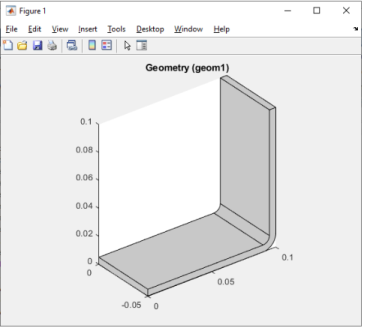
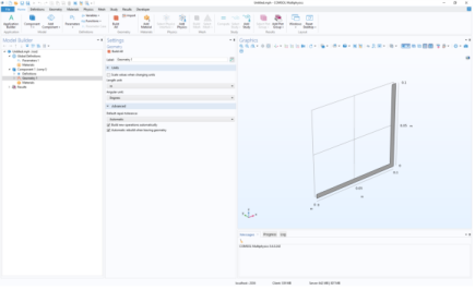
The initial geometry is obtained by extruding a 2D drawing. Create a work plane tagged 'wp1', and set it as the xz-plane of the 3D geometry:
|
|
5
|
|
6
|
Create a second rectangle and set the width to L+tbb and the height to 0.1-tbb. Then change the rectangle position to (0;tbb):
|
|
7
|
Subtract rectangle r2 from rectangle r1, by creating a Difference feature with the 'input' property set to r1 and the 'input2' property set to r2:
|
|
8
|
Round the inner corner by creating a Fillet feature and set point 3 in the selection property. Then set the radius to tbb:
|
|
9
|
Round the outer corner by creating a new Fillet feature, then select point 6 and set the radius to 2*tbb:
|
|
10
|
Extrude the geometry objects in the work plane. Create an Extrude feature, set the work plane wp1 as input and the distance to wbb:
|
|
11
|
Create a new work plane and set the planetype property to faceparallel. Then set the selection to boundary 8:
|
|
12
|
|
13
|
Create an Extrude node, select the second work plane wp2 as input, and then set the extrusion distance to -2*tbb:
|
|
14
|
|
15
|
Create a circle, then set the radius to rad_1 and set the position of the center to (-L/2+1.5e-2;-wbb/4):
|
|
16
|
Create a second circle in the work plane by copying the previous circle and displacing it a distance wbb/2 in the y direction:
|
|
17
|