Using Mesh Control Entities to Control Element Size
Figure 8-14 shows a 2D geometry with two holes and a Bézier Polygon that is intended not to be a part of the model but is included only to control mesh size inside the domain. This example is about Mesh Control Entities and uses a simple geometry.
1
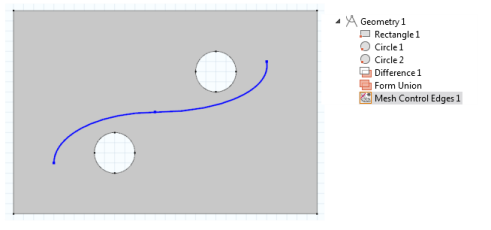
Add a Mesh Control Edges () node from the Geometry toolbar, Virtual Operations menu () (or right-click the Geometry node and select it from the Virtual Operations submenu).
2
Figure 8-14: A geometry with a Bézier Polygon used to define mesh size inside the domain.
3
Click Build Selected (). Note that the selected edges are removed.
4
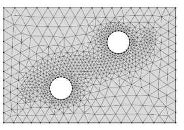
Add a Free Triangular () node from the Mesh toolbar. Note that the edges removed in the previous step are now visible again.
5
Add a Size () node to Free Triangular 1.
6
7
Select Extra fine as the Predefined element size.
8
Click the Build All button () or press F8 to build the entire mesh. Note that the edges of the Bézier Polygon are now removed (Figure 8-15) and that the only trace of them is the fine mesh size inside the domain.
Figure 8-15: Fine mesh inside the domain.
Mesh Control Feature Model Examples
For an example of the Mesh Control Edges feature:
In the CFD Module, see Turbulent Flow over a Backward-Facing Step: Application Library path CFD_Module/Verification_Examples/turbulent_backstep.
In the Heat Transfer Module, see Turbulent Flow over a Backward-Facing Step: Application Library path Heat_Transfer_Module/Verification_Examples/turbulent_backstep.
For an example of the Mesh Control Faces feature:
In the Battery Design Module, see Thermal Modeling of a Cylindrical Lithium-Ion Battery in 3D: Application Library path Battery_Design_Module/Thermal_Management/li_battery_thermal_3d.
In the CFD Module, see Airflow over an Ahmed Body: Application Library path CFD_Module/Verification_Examples/ahmed_body.