Meshing Examples
Generating a 3D Swept Mesh
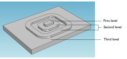
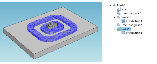
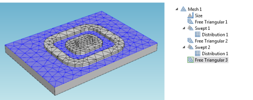
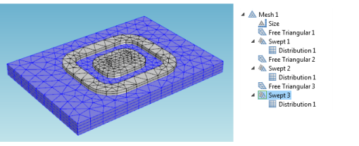
Figure 8-13 shows the 3D Swept mesh for a simple geometry but with a layered structure typical for printed circuit boards or MEMS geometries. In such cases, the swept mesh generation presents an alternative to using a free tetrahedral meshing.
Acoustics Module, see Vibrations of a Disk Backed by an Air-Filled Cylinder: Application Library path Acoustics_Module/Verification_Examples/coupled_vibrations.
Fuel Cell & Electrolyzer Module, see Ohmic Losses and Temperature Distribution in a Passive PEM Fuel Cell: Application Library path Fuel_Cell_and_Electrolyzer_Module/Thermal_Management/passive_pem.
Electrodeposition Module, see Electrodeposition of an Inductor Coil: Application Library path Electrodeposition_Module/Tutorials/inductor_coil.
Chemical Reaction Engineering Module, see Steam Reformer: Application Library path Chemical_Reaction_Engineering_Module/Reactors_with_Porous_Catalysts/steam_reformer.
Figure 8-13: An example of the layered geometry used for creating a swept mesh.
1
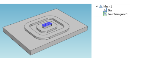
Add a Free Triangular () node from the Mesh toolbar, Boundary menu () (or right-click the Mesh node and select it from the More Operations menu).
2
3
Click Build Selected (). The mesh below displays.
4
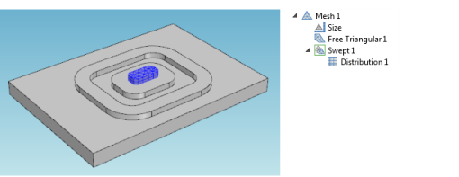
Add a Swept () node from the Mesh toolbar.
5
6
Add a Distribution () node to the Swept 1 node.
7
Enter the Number of elements in the field (for example, 2).
8
Click Build Selected ().
9
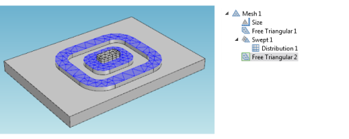
Add a second Free Triangular () node from the Mesh toolbar.
10
11
12
Add a third Free Triangular mesh operation to mesh the third level boundaries.
13
Mesh the third level domain. Use the Swept mesh operation and enter 4 for the Number of elements in the corresponding Distribution attribute.
The meshing sequence displayed in the Model Builder makes it possible to return to your attribute settings and change mesh sizes and distributions. After making any changes, click the Build All button () or press F8 to rebuild the entire meshing sequence.