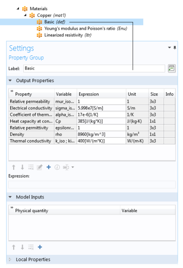
The Settings window for
Property Group is where output properties and model inputs are added, local properties are defined, and expressions for material properties are entered in a specific property group such as
Basic. The property groups are subnodes to a material node. The
Settings window for
Property Group is displayed when you click the property group node (for example,
Basic) under the material node (typically with the material’s name —
Aluminum, for example) in the
Model Builder.
Click the Add button (

) to add another output property, which you choose from one of the available physical quantities in the
Physical Quantity dialog box that opens.
If required, edit the expressions in the list’s Expression column. Edit directly in the table or in the
Expression field underneath the table. You can insert predefined expressions by clicking the
Insert Expression button (

) or clicking Ctrl+Space and then choosing an expression from the list of predefined expressions. You can also click the
Edit button (

), which opens a dialog box for easier specification of orthotropic and anisotropic material properties (tensors), when applicable. Select
Isotropic,
Diagonal,
Symmetric, or
Full when entering the data in the material property’s dialog box. In the
Expression column, use a syntax with curly braces such as
{k11, k21, k31, k12, k22, k32, k13, k23, k33} to enter anisotropic material properties for a 3-by-3 tensor
kij in the order
k11,
k21,
k31,
k12,
k22,
k32,
k13,
k23, and
k33. 1, 2, and 3 represent the first, second, and third direction in the active coordinate system. In many cases (for example, when entering the elasticity matrix for structural mechanics), the matrix must for physical reasons be symmetric. The upper diagonal part of the matrix you enter will then be mirrored when forming the actual constitutive matrix, and the lower diagonal part is ignored.
The Variable column lists the variable names depending on the type of anisotropy. For an isotropic
k,
k_iso represents its single scalar value.
The Unit and
Size columns provide information about the unit and size of the output property. The size is 1x1 for a scalar value such as density and 3x3 for a tensor (matrix) quantity such as electrical conductivity.
If desired, you can add information about the property, such as references for its value or expression. To do so, click the Edit/Show Property Information button (

) and enter the property information in the dialog box that opens and then click
OK. When information is available for a property, and information symbol (

) appears in the
Info column.
Use the Move up (

),
Move down (

), and
Delete (

) buttons to organize the table as needed.
The model inputs are physical quantities, such as temperature, that are used as inputs in the expressions that define the output properties (for example, to describe a temperature-dependent physical quantity). For example, adding Temperature as a model input with the variable name
T makes it possible to use an expression for the heat capacity at constant pressure
Cp, such as
300[J/(kg*K)]*T[1/K], which works regardless of the name of the actual dependent variable for temperature in the model that uses the temperature-dependent material. Without the model input, the expression above only works with a temperature variable called
T.
Click the Add button (

) to add another model input, which you choose from one of the available physical quantities in the
Physical Quantity dialog box that opens.
Use the Move up (

),
Move down (

), and
Delete (

) buttons to organize the table as needed.
Here you can enter a user-defined property by entering its variable name in the Name column and its corresponding
Expression and organizing the table as needed. You can also enter a
Description, which appears in the
Property column in the
Material Contents section of the parent
Material node. In that node, the
Name entered here appears in the
Variable column. These local properties are useful for parameterizing functions that describe material properties if they contain inputs other than those that are model inputs (such as temperature and pressure). For example, a local property can be a reference value at a certain temperature. Use the
Move up (

),
Move down (

), and
Delete (

) buttons to organize the tables as needed.
Material property groups are automatically added to the material node in the Model Builder. You can also add additional predefined property groups or create a
User-Defined Property Group (on the
Materials toolbar, click
User-defined Property Group (

) or right-click the
Material node). The available properties are collected in property groups according to the physical context.
Each property group has a Settings window for
Property Group. When a
Model Builder node is clicked (for example,
Basic), the
Settings window for
Property Group displays specific information about that property group. The physical properties for all property groups are summarized in a
Material Contents table on the
Settings window for the parent
Material node.