You are viewing the documentation for an older COMSOL version. The latest version is
available here.
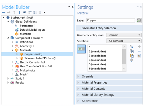
The Settings window for
Material (

) summarizes the predefined or user-defined material properties for a material. This is where you can add or change material properties to fit your model and assign the material to all types of geometric entities: domains (most common), boundaries, edges (3D models only), or points. Also see
Material Link and
Switch for Materials.
After adding a material (see The Add Material Window and
The Material Browser Window), click the Material node (for example,
Material 1 or
Copper) in the
Model Builder. The
Settings window for
Material opens.
A standard Material node in the global component can turn into a layered material by adding a
Shell property group. After that, it can be linked by a
Layered Material Link
In the Label field, enter a suitable name for the material. If you defined global materials for a user-defined material library, the label becomes the name of the material. See also
Material Library Settings below.
This section is available for materials in a component. Assign the material to some or all entities on a specific Geometric entity level —
Domain,
Boundary,
Edge (3D only), or
Point — on the geometry in the
Graphics window (the geometry in the model).
The Overridden by list shows the names of the materials that override this material. The
Selection list in the
Geometric Entity section displays
(overridden) for the geometric entities in which this material is overridden.
The Overrides list shows the names of the materials that this material overrides.
Select a Coordinate system defining the principal directions of the laminate. Only
Boundary System coordinate systems can be selected.
Choose a Position —
Midplane on boundary,
Downside on boundary,
Upside on boundary, or
User defined. This controls the possible offset of the material from the geometrical boundary on which the mesh exists (the
reference surface). For
User defined, enter a value for the
Relative midplane offset. The value
1 corresponds to
Downside on boundary, and the value
−1 corresponds to
Upside on boundary. Values may be outside the range
−1 to 1, in which case the reference surface is outside the laminate.
The Position setting is only used by physics features where the physical behavior depends of the actual location, such as structural shells.
By clicking the Layer Cross Section Preview (

) button, you get a preview plot of the single layer material, including the location of the reference surface. This plot looks similar to
Figure 9-12, but there is only a single layer. You can also click the downward pointing arrow to choose
Layer Cross Section Preview (

) button or
Create Layer Cross Section Preview (

) button, which adds the preview plot as a new plot group under
Results.
You can add material properties to the material if they are not already included. To do so, browse the available material property categories (Basic Properties,
Acoustics, and so on), and select a material property or a collection of material properties in one of the property groups or material models that appear under the main level of material property categories. Right-click the material property or property group and select
Add to Material, or click the
Add to Material button (

) to add the material property or group of properties to the material.
For example, under Acoustics>Viscous Model select
Bulk viscosity (muB) and right-click to
Add to Material or click the
Add to Material button (

). If you add a material model like the
Viscous Model with more than one property, all of its material properties are added to the
Material Contents table. In this example, a
Viscous model node is added to the
Model Builder and its associated properties are added to the
Material Contents table.
Material properties can be added to the Basic group or to any
User-Defined Property Group from two locations — the
Settings windows for
Material and
Property Group.
|
•
|
When material properties are added from the Settings window for Material, the available material properties are listed under Material Properties and are added to the list under Material Contents with the property group listed. The list under Material Contents also contains material properties added from a subnode with a Settings window for Property Group.
|
The Material type setting decides how materials behave and how material properties are interpreted when the mesh is deformed. Select
Solid for materials whose properties change as functions of material strain, material orientation, and other variables evaluated in a material reference configuration (material frame). Select
Nonsolid for materials whose properties are defined only as functions of the current local state at each point in the spatial frame and for which no unique material reference configuration can be defined.
Simply put, Solid materials associate material properties with specific pieces of the material, and the properties follow the material as it moves around. In particular, a solid material may be inherently anisotropic, meaning that its axes rotate together with the material. The
Nonsolid choice, in contrast, applies typically to liquids and gases whose properties are associated with fixed points in space and insensitive to local rotation of the material. Such materials are inherently isotropic when studied in isolation but can exhibit anisotropy induced by external fields. In practice, this means that any anisotropic tensor properties in a nonsolid material must be functions of some external vector field.
This section lists all of the material properties that are defined for the material or required by the physics in the model. The table lists the Property,
Variable,
Value, and
Unit for the material property as well as the
Property group to which the material property belongs. The
Property group corresponds to the subnodes in the
Model Builder with the same name. If required, edit the values or expression for the property’s
Value.
|
•
|
A stop sign ( ) indicates that an entry in the Value ) indicates that an entry in the Value column is required. It means that the material property is required by a physics feature in the model but is undefined. When you enter a value in the Value column, the material property is added to its property group.
|
You can change the value for any property that is not synchronized by editing its value directly in the Value column, or, for a selected property, click the
Edit button (

) to enter a value in the window that opens. If the property can be anisotropic, you can choose to enter the values in one of these forms:
Isotropic,
Diagonal,
Symmetric, or
Full. The
Variable column lists the variable names corresponding to the degree of anisotropy. For example, for a symmetric electrical conductivity, it contains
{sigma11, sigma12, sigma22, sigma13, sigma23, sigma 33}; sigmaij = sigmaji. For an isotropic electrical conductivity, it contains
sigma_iso; sigmaii = sigma_iso, sigmaij = 0, where
sigma_iso is the name of the variable for the isotropic electrical conductivity (available as, for example,
mat1.def.sigma_iso).
|
|
Select the Material Library Settings check box in the Show More Options dialog box to display this section for Material nodes under Global Definitions.
|
Click the Update the Label button (

) to update the label, which becomes the name of the material in the user-defined material library.
From the Phase list, choose
Custom,
Solid,
Liquid, or
Gas to define the material’s phase. This setting is not available if the parent
Group node has its
Group type set to
Phase and orientation, in which case the phase is defined in that
Group node’s settings.
In the Orientation/variation field, enter some orientation or variation that represent this material.
The Material type list provides quick settings approximating the appearance of a number of materials —
Air,
Aluminum,
Brick,
Concrete,
Copper,
Glass,
Gold,
Iron,
Lead,
Magnesium,
Oil,
Plastic,
Rock,
Soil,
Steel,
Titanium,
Water,
Wood, and more. Select
Custom to make further adjustments of the specific settings for colors, texture, reflectance, and so on. The default custom settings are inherited from the material selected last from the
Material type list. If you have chosen a family other than
Custom, click the Customize button to define a custom material.
For each of these properties, select a standard color from the list: Black,
Blue,
Cyan,
Gray,
Green,
Magenta,
Red,
White, or
Yellow, or choose
Custom button to define a custom color from the color palette that becomes available underneath the list of colors.
The combination of Specular color,
Diffuse color, and
Ambient color gives a 3D object its overall color:
|
•
|
Specular color is the color of the light of a specular reflection (specular reflection is the type of reflection that is characteristic of light reflected from a shiny surface).
|
|
•
|
Diffuse color represents the true color of an object; it is perceived as the color of the object itself rather than a reflection of the light. The diffuse color gets darker as the surface points away from the light (shading). As with Ambient color, if there is a texture, this is multiplied by the colors in the texture, otherwise it is as if it has a white texture.
|
|
•
|
Ambient color is the color of all the light that surrounds an object; it is the color seen when an object is in low light. This color is what the object reflects when illuminated by ambient light rather than direct light. Ambient color creates the effect of having light hit the object equally from all directions. As with Diffuse color, if there is a texture, this is multiplied by the colors in the texture; otherwise, it is as if it has a white texture.
|
The Normal mapping check box is selected by default, with the default
Normal vector noise scale and
Normal vector noise frequency taken from the material. You can choose the type from the
Noise type list:
White noise (a uniform distribution) or
Simplex noise.
Select the Additional color check box if you want to blend the appearance with an additional color that is added on the surface using noise. The settings are similar to those for the normal mapping above, but you can also choose the color to add from the
Color list and choose a
Color blend between 0 and 1. The
Noise color is a parameter that affects the appearance of the added color.
The default Opacity is 1.
The default Lighting model —
Blinn-Phong or
Cook-Torrance — is based on the material. Select
Simple instead as needed; it has no additional settings.
For Blinn-Phong, the default
Specular exponent is 64. The specular exponent determines the size of the specular highlight. Typical values for this property range from 1 to 500, with normal objects having values in the range 5 to 20. This model is particularly useful for representing shiny materials.
For Cook-Torrance, the default settings are taken from the material. The Cook–Torrance lighting model accounts for wavelength and color shifting and is a general model for rough surfaces. It is targeted at metals and plastics, although it can also represent many other materials, and it includes the following settings.
|
•
|
The Reflectance at normal incidence value is the amount of incoming light from the normal direction (of the surface) that is reflected.
|
|
•
|
The Surface roughness is a value that describes microreflectance on the surface. Higher values create a rougher look of the surface with fewer highlights.
|
|
•
|
The Metallic parameter is a value that affects how metallic the material appears to be. A less metallic material reflects less of the environment. A nonmetallic material cannot reflect the environment
|
|
•
|
The Pearl parameter is an artificial effect that mimics the colors of a pearl.
|
|
•
|
The Diffuse wrap value gives an artificial effect that you can use to emulate subsurface scattering.
|
|
•
|
The Clear coat parameter is an artificial effect that makes surfaces that are parallel to the view direction more white. It also adds specular highlighting and reduces the effect on the environment reflections from the normal mapping.
|
|
•
|
The Reflectance value is an additional setting that affects how much of the environment that is reflected.
|