You are viewing the documentation for an older COMSOL version. The latest version is available here.
Tutorial Example — Backstep
This tutorial solves the incompressible Navier-Stokes equations in a backstep geometry. A characteristic feature of fluid flow in geometries of this kind is the recirculation region that forms where the flow exits the narrow inlet region. The application demonstrates the modeling procedure for laminar flows in the CFD Module.
Model Geometry
The model consists of a pipe connected to a block-shaped duct (see Figure 7). Due to symmetry, it is sufficient to model one eighth of the full geometry.
Figure 7: The model geometry showing the symmetry.
Domain Equations and Boundary Conditions
The flow in this model is laminar and you should therefore use the Laminar Flow interface.
The inlet flow is fully developed, which will be specified by the corresponding inlet boundary condition. This boundary condition computes the flow profile for fully developed flow in a channel of arbitrary cross section. The boundary condition at the outlet sets a constant relative pressure. Furthermore, the vertical and inclined boundaries along the length of the geometry are symmetry boundaries. All other boundaries are solid walls described by a no-slip boundary condition.
Results
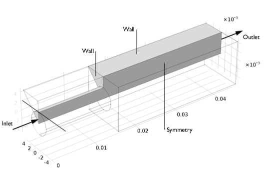
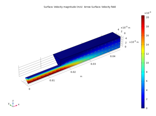
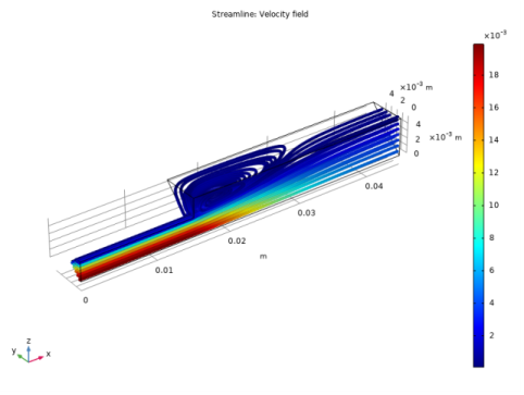
Figure 8 shows a combined surface and arrow plot of the flow velocity. This plot does not reveal the recirculation region in the duct immediately beyond the inlet pipe’s end. For this purpose, a streamline plot is more useful, as shown in Figure 9.
Figure 8: The velocity field in the backstep geometry.
Figure 9: The recirculation region visualized using a velocity streamline plot.
The following instructions show how to set up the model, solve it, and reproduce these plots.