Battery Modeling
The Battery Design Module has a number of physics interfaces to model batteries. Choice of physics interface depends on the overall purpose of the model. When studying the cell chemistry, aging or high charge-discharge rates one typically resolves the different layers of the battery using space-dependent models on a micrometer scale, whereas coarser models for computing heat sources or predicting the voltage behavior for low or moderate charge-discharge rates may use a more lumped modeling approach.
Space-dependent battery models often model unit cells that consist of:
a) Current collectors and current feeders
b) Porous or solid metal electrodes
c) The electrolyte that separates the anode and cathode
To exemplify we describe some of the charge and discharge processes in a rechargeable battery below.
Figure 2: Direction of the current and charge transfer current during discharge in a battery with porous electrodes.
During discharge, chemical energy is transferred to electrical energy in the charge transfer reactions at the anode and cathode. The conversion of chemical to electrical energy during discharge may involve electrochemical reactions, transport of electric current, transport of ions and neutral species in the electrolyte, mass transport in the electrode particles, fluid flow, and the release of heat in irreversible losses, such as ohmic losses and losses due to activation energies.
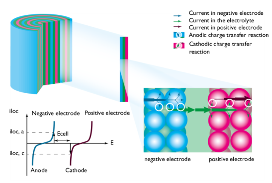
Figure 2 shows a schematic picture of the discharge process. The current enters the cell from the current feeder at the negative electrode. The charge transfer reaction occurs at the interface between the electrode material and electrolyte contained in the porous electrode, also called the pore electrolyte. Here, an oxidation of the electrode material may take place through an anodic charge transfer reaction, denoted iloc, a in Figure 2. The shapes of the two curves in the graph are described by the electrode kinetics for the specific materials. The reaction may also involve the transport of chemical species from the pore electrolyte and also from the electrode particles.
From the pore electrolyte, the current is conducted by the transport of ions through the electrolyte that separates the positive and negative electrode (via separator or reservoir) to the pore electrolyte in the positive electrode.
At the interface between the pore electrolyte and the surface of the particles in the porous electrode, the charge transfer reaction transfers the electrolyte current to current conducted by electrons in the positive electrode. At this interface, a reduction of the electrode material takes place through a cathodic charge transfer reaction, denoted iloc, c in Figure 3. Also here, the charge transfer reaction may involve the transport of chemical species in the electrolyte and in the electrode particles.
Figure 3: Electrode polarization during discharge. The figure is same as inset of Figure 2.
The current leaves the cell through the current collector. The conduction of current and the electrochemical charge transfer reactions also release heat due to ohmic losses, activation losses, and other irreversible processes.
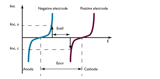
The graph in Figure 3 plots the charge transfer current density, iloc, as a function of the electrode potential, E. These curves describe the polarization of the electrodes during discharge.
The negative electrode is polarized anodically during discharge, a positive current as indicated by the arrow in Figure 3. The potential of the negative electrode increases. The positive electrode is polarized cathodically, a negative current as indicated by the arrow. The potential of the positive electrode decreases.
Consequently, Figure 3 also shows that the potential difference between the electrodes, here denoted Ecell, decreases during discharge compared to the open cell voltage, here denoted Eocv. The value of Ecell is the cell voltage at a given current iloc, if the ohmic losses in the cell are negligible. This is usually not the case in most batteries. This implies that the cell voltage in most cases is slightly smaller than that shown in Figure 3.
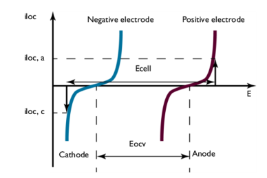
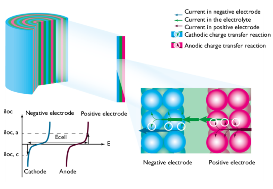
During charge, the processes are reversed; see Figure 4. Electrical energy is transformed to chemical energy that is stored in the battery.
Figure 4: During charge, the positive electrode acts as the anode while the negative one acts as the cathode. The cell voltage increases (at a given current) compared to the open cell voltage. Note: direction of the currents is reversed here.
The current enters the cell at the positive electrode. Here, during charge, an oxidation of the products takes place through an anodic charge transfer reaction. The positive electrode is polarized anodically, with a positive current, and the electrode potential increases.
The current is then conducted via pore electrolyte, through the electrolyte in a separator (or a reservoir) that separates the electrodes, to the negative electrode.
In the negative electrode, a reduction of the products from the previous discharge reaction takes place through a cathodic charge transfer reaction. The negative electrode is polarized cathodically and the electrode potential decreases.
Figure 5: Electrode polarization during charge.
The difference in potential between the electrodes, here denoted Ecell, at a given iloc, increases during charge, compared to the open cell voltage, here denoted Eocv; see Figure 5. The value of Ecell is equal to the cell voltage when ohmic losses are neglected. In most cells, these losses are not negligible and they would add to the cell voltage.
The battery processes and phenomena described in the figures above can all be investigated using the Battery Design Module. The physics interfaces included in the module allow you to investigate the influence on battery performance and thermal management of parameters such as the:
The Battery Modeling Physics Interfaces
The Lithium-Ion Battery interface () is tailored for lithium-ion batteries using liquid electrolytes and includes functionality that describes the transport of charged species in porous electrodes, electrolyte, intercalation reactions in electrodes, binders, charge transfer reactions, internal particle diffusion, temperature dependence of transport quantities, aging mechanism, and the solid electrolyte interface (SEI).
The Lithium-Ion Battery, Single-Ion Conductor interface () is similar to the above interface, but uses a different default for charge-balance equation in the electrolyte, typically suitable for solid electrolytes.
The Single Particle Battery interface () offers a simplified (compared to for instance the Lithium-Ion Battery interface) approach to battery modeling. This interface models the charge distribution in a battery using one separate single particle model each for the positive and negative electrodes of the battery. It accounts for solid diffusion in the electrode particles, the intercalation reaction kinetics and ohmic potential drop in the separator using a lumped solution resistance term.
The Battery with Binary Electrolyte interface () describes the conduction of electric current in the electrodes, the charge transfer reactions in the porous electrodes, the mass transport of ions in the pore electrolyte and in the electrolyte that separates the electrodes, and the intercalation of species in the particles that form the porous electrodes. The descriptions are available for cells with basic binary electrolyte, which covers the nickel-metal hydride and the nickel-cadmium batteries.
The Lumped Battery interface () defines a battery model based on a small set of lumped parameters, requiring no knowledge of the internal structure or design of the battery electrodes, or choice of materials. Models created with the Lumped Battery interface can typically be used to monitor the state-of-charge and the voltage response of a battery during a load cycle. The interface also defines a battery heat source that may be coupled to a Heat Transfer interface for modeling battery cooling and thermal management.
The Battery Equivalent Circuit () can be used to define a battery model based on an arbitrary number of electrical circuit elements. Models created with the Battery Equivalent Circuit can typically be used to monitor the state-of-charge and the voltage response of a battery during a load cycle. When selecting the Battery Equivalent Circuit in the Model Wizard, this adds an Electrical Circuit () interface to the model, including a number of predefined circuit elements that are used to define the open circuit voltage, the load current and an internal resistance. Additional circuit elements such as resistors, capacitors, and inductors may be added by the user.
The Lead-Acid Battery interface () is tailored for this type of battery and includes functionality that describes the transport of charged species, charge transfer reactions, the variation of porosity due to charge and discharge, and the average superficial velocity of the electrolyte caused by the change in porosity.
The Tertiary Current Distribution, Nernst-Planck interface () describes the transport of charged species in electrolytes through diffusion, migration, and convection. In addition, it also includes ready-made formulations for porous and non-porous electrodes, including charge transfer reactions and current conduction in the electronic conductors.
The Chemical Species Transport interfaces () describe the transport of ions in the pore electrolyte and in the electrolyte that separates the anode and cathode. Other reactions can be added other than pure electrochemical reactions to, for example, describe the degradation of materials. In combination with the Secondary Current Distribution interface (), the Transport of Concentrated Species interface (), and the Transport of Diluted Species in Porous Media interface () can be used to model the transport of charged species and the electrochemical reactions in most battery systems.
The Chemistry interface (), found within the Chemical Species Transport branch, can be used to define systems of reacting species, electrode reactions and ordinary chemical reactions. As such, it serves as a reaction kinetics and material property provider to the space-dependent transport interfaces, such as the Tertiary Current Distribution, Nernst–Planck interface, or Transport of Diluted Species interface.
The Fluid Flow interfaces () describe the fluid flow in the porous electrodes and in free media if this is relevant for a specific type of battery, for example, certain types of lead-acid batteries.
The Heat Transfer in Porous Media interface () describes heat transfer in the cells. This includes the effects of Joule heating in the electrode material and in the electrolyte, heating due to activation losses in the electrochemical reactions, and of the net change of entropy. The heat from reactions other than the electrochemical reactions can also be described by these physics interfaces.