Singular Loads
In reality, loads always act on a finite area. However, in a model a load is sometimes defined on a point or an edge, which leads to a singularity. The reason for this is that points and lines have no area, so the stress becomes infinite. Because of the stress singularity, there are high stress values in the area surrounding the applied load. The size of this area and the magnitude of the stresses depend on both the mesh and the material properties. The stress distribution at locations far from these singularities is unaffected according a to a well-known principle in solid mechanics, the St. Venant’s principle. It states that for an elastic body, statically equivalent systems of forces produce the same stresses in the body, except in the immediate region where the loads are applied.
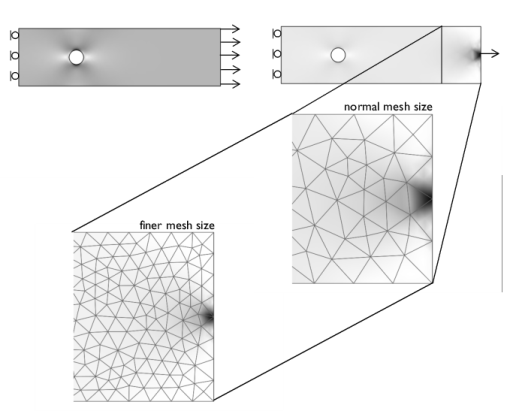
Figure 2-5 shows a plate with a hole in plane stress loaded with a distributed load and a point load of the same magnitude. The mesh consists of triangular elements with quadratic shape functions. The high stress around the point load is dissipated within the length of a few elements for both mesh cases. The stresses in the middle of the plate and around the hole are in agreement for the distributed load and the point load. The problem is that due to the high stress around the singular load it is easy to overlook the high stress region around the hole. When the point load is applied, the range must be manually set for the stress plot to get the same visual feedback of the high stress region around the hole in the two cases. This is because the default plot settings automatically set the range based on the extreme values of the expression that is plotted.
Despite these findings it is good modeling practice to avoid singular loads because it is difficult to estimate the size of the singular region. In the Structural Mechanics Module it is possible to define loads on all boundary types. However, avoid singular loads altogether with elastoplastic or creep materials.
The Plasticity and Creep nodes are available as a subnode to Linear Elastic Material nodes with the Nonlinear Structural Materials Module or the Geomechanics Module.
Figure 2-5: A plate with a hole subject to a distributed load (left) and a point load (right).