The RF Module Physics Interfaces
The RF Module physics interfaces are based on Maxwell’s equations or subsets and special cases of these together with material constitutive relations. In the module, these laws of physics are translated by the RF interfaces to sets of partial differential equations with corresponding initial and boundary conditions.
The RF interfaces define a number of features. Each feature represents a term or condition in the underlying equations and may be defined in a geometric entity of the model, such as a domain, boundary, edge (for 3D components), or point.
Figure 8: The Model Builder (left), and the Settings window for Wave Equation, Electric (right). The Equation section shows the model equations and the terms added by the Wave Equation, Electric 1 node to the model equations. The added terms are underlined with a dotted line. The text also explains the link between the Dielectric node and the values for the relative permittivity.
Figure 8 uses the Coaxial Waveguide Coupling model from the RF Module application library to show the Model Builder window and the Settings window for the selected Wave Equation, Electric 1 feature node. The Wave Equation, Electric 1 node adds the terms representing Electromagnetic Waves to the model equations in a selected geometrical domain in the model.
Furthermore, the Wave Equation, Electric 1 feature node may link to the Materials feature node to obtain physical properties such as relative permittivity — in this case the relative permittivity of a user-defined dielectric. The properties, defined by the Dielectric material, can be functions of the modeled physical quantities, such as temperature. In the same fashion, the Perfect Electric Conductor 1 feature adds a reflecting boundary condition to truncate the modeling domain.
Figure 9 shows the Radio Frequency (RF) interfaces as displayed in the Model Wizard for this module.
Figure 9: The Radio Frequency (RF) physics interfaces as displayed in the Model Wizard.
This module includes RF interfaces () for both frequency-domain and time-domain modeling. It also includes the Microwave Heating interface that is found under Heat Transfer>Electromagnetic Heating. Also see Physics Interface Guide by Space Dimension and Study Type. A brief overview of the RF interfaces follows.
Electromagnetic waves, Frequency Domain
The Electromagnetic Waves, Frequency Domain interface () solves a frequency-domain wave equation for the electric field. The sources can be in the form of point dipoles, line currents, or incident fields on boundaries or domains. It is used primarily to model electromagnetic wave propagation in different media and structures. This physics interface can also be used to solve an eigenvalue problem for the resonant frequencies and fields of a structure, or to find the propagating modes of a waveguide or transmission line. Some typical applications that are simulated with this physics interface are waveguides and transmission lines, filters and resonators, antennas, and RF connectors and couplers.
Electromagnetic waves, Time Explicit
The Electromagnetic Waves, Time Explicit interface () solves a system of two first-order partial differential equations (Faraday’s law and Maxwell-Ampère’s law) for the electric and magnetic fields using the Time Explicit Discontinuous Galerkin method. The sources can be in the form of volumetric electric or magnetic currents or electric surface currents or fields on boundaries. It is used primarily to model electromagnetic wave propagation in linear media. Typical applications involve the transient propagation of electromagnetic pulses.
Electromagnetic waves, Transient
The Electromagnetic Waves, Transient interface () solves a time-domain wave equation for the electric field. The sources can be in the form of point dipoles, line currents, or incident fields on boundaries or domains. It is used primarily to model electromagnetic wave propagation in different media and structures when a time-domain solution is required — for example, non-sinusoidal waveforms or nonlinear media. Typical applications involve the propagation of electromagnetic pulses and the generation of harmonics in nonlinear optical media.
Transmission Line
The Transmission Line interface () solves the time-harmonic transmission line equation for the electric potential. This physics interface is used when solving for electromagnetic wave propagation along one-dimensional transmission lines and is available in 1D, 2D and 3D. Eigenfrequency and Frequency Domain study types are available. The frequency domain study is used for source-driven simulations at a single frequency or a sequence of frequencies. Typical applications involve the design of impedance matching elements and networks.
Microwave Heating
The Microwave Heating interface () combines the features of the Electromagnetic Waves, Frequency Domain interface with those of the Heat Transfer interface. A predefined interaction automatically sets the electromagnetic losses as sources for the heat equation. This physics interface is based on the assumption that the electromagnetic cycle time is short compared to the thermal time scale (adiabatic assumption).
Electrical Circuit
The Electrical Circuit interface () can be connected to an RF interface. The lumped voltage and current variables from the circuits are translated into boundary conditions applied to the distributed field model. Typical applications include the modeling of transmission lines and antenna feeding.
Physics Interface Guide by Space Dimension and Study Type
The table below lists the physics interfaces available specifically with this module in addition to the COMSOL Multiphysics basic license.
AC/DC
stationary; frequency domain; time dependent; small signal analysis, frequency domain
Heat Transfer
Electromagnetic Heating
Radio Frequency
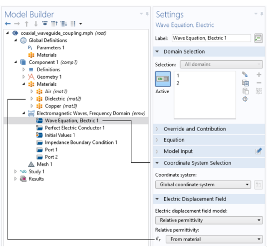
1 This physics interface is a predefined multiphysics coupling that automatically adds all the physics interfaces and coupling features required.