Introduction
The Plasma Module is tailor-made to model and simulate low-temperature plasma sources and systems. Engineers and scientists use it to gain insight into the physics of discharges and gauge the performance of existing or potential designs. The module can perform analysis in all space dimensions — 1D, 2D, and 3D — although it is very rare in the plasma modeling community to do 3D modeling. Plasma systems are, by their very nature, complicated systems with a high degree of nonlinearity. Small changes to the electrical input or plasma chemistry can result in significant changes in the discharge characteristics.
Low-temperature plasmas represent the amalgamation of fluid mechanics, reaction engineering, physical kinetics, heat transfer, mass transfer, and electromagnetics. The Plasma Module is a specialized tool for modeling non-equilibrium and equilibrium discharges, which occur in a wide range of engineering disciplines.
The Plasma Module consists of a suite of physics interfaces that allow arbitrary systems to be modeled, a set of documented examples, and a manual. The intended audience is researchers and engineers with a background in the physics of low-temperature discharges.
Applications of Plasmas in Science & Technology
There are many different types of plasma that are typically of interest. The main difference between the plasmas is that the mechanism of energy transfer between the electrons and fields is different. In this section the following types of plasma are discussed:
Direct Current Discharges
Direct current (DC) discharges are sustained through secondary electron emission at the cathode due to ion bombardment. The electrons ejected from the cathode are accelerated through the cathode fall region into the bulk of the plasma. They may acquire enough energy to ionize the background gas, creating a new electron-ion pair. The electron makes its way to the anode whereas the ion will migrate to the cathode, where it may create a new secondary electron. It is not possible to sustain a DC discharge without including secondary electron emission.
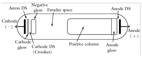
Several distinct regions typically exist in a DC discharge, depending on the specific operating conditions and geometry. A typically DC discharge is shown below. The cathode glow (often known as cathode fall) region is where most of the voltage drop occurs. This is the region where the discharge current is built up due to the high degree of ionization. The electron density and flux grow exponentially in this region (Ref. 5). The negative glow and Faraday space regions connect the cathode glow to the positive column. In this region the electron temperature drops rapidly due to the fact that the electric field is very weak. In the positive column region, the discharge is very uniform, and the electron-ion pairs generated are lost to the walls in the radial direction due to the ambipolar field (Ref. 5).
Diagram showing the most important regions in a typical DC discharge, after Ref. 5.
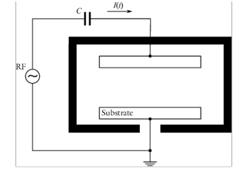
DC discharges can easily begin to arc, especially at high pressures. Arcing is typically undesirable so, in practice, a ballast resistor or series RC circuit is placed between the power supply and the cathode. As the discharge current at the cathode begins to increase, the voltage applied at the cathode will begin to drop due to the presence of the RC circuit. If the ballast resistance is high enough, the DC discharge will remain smooth and uniform and not begin to arc. The pressure range for a DC discharge is typically in the range of 10 Pa all the way up to atmospheric pressure and the applied voltage is typically several hundred volts all the way up to several kV.
Schematic of a positive column DC discharge including an external circuit. The ballast resistor and blocking capacitor prevent the discharge from arcing.
Inductively coupled plasmas
Inductively coupled plasmas (ICP) were first used in the 1960s as thermal plasmas in coating equipment, Ref. 4. These devices operated at pressures on the order of 0.1 atm and produced gas temperatures on the order of 10,000 K. In the 1990s, ICP became popular in the film processing industry as a way of fabricating large semiconductor wafers. These plasmas operated in the low-pressure regime, from 0.002–1 Torr and, as a consequence the gas temperature remained close to room temperature. Low-pressure ICP are attractive because they provide a relatively uniform plasma density over a large volume. The plasma density is also high, around 1018 1/m3, which results in a significant ion flux to the surface of the wafer. Faraday shields are often added to reduce the effect of capacitive coupling between the plasma and the driving coil. This reduces the effect of ion bombardment on the dielectric window, which can lead to degradation and contamination of the chamber. Some typical ICP configurations are shown in the figure below.
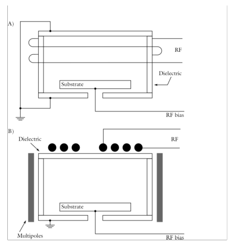
Sketch of some typical ICP configurations used in the semiconductor processing industry, after Ref. 5.
From an electrical point of view, inductively coupled plasmas act like transformers, with the driving coil acting as the primary and the plasma acting as the secondary. The current flowing through the coil induces a current in the plasma, causing the electrons to flow in the opposite direction to the current flowing in the coil. This, in turn, induces an opposing current back in the coil. The coil and plasma are strongly coupled. Heating of the electrons only occurs within the skin depth of the plasma. The higher the plasma density or the applied frequency, the smaller the volume over which power is deposited from the fields to the electrons. The design and operating frequency of the coil should be such that the plasma is uniform over the reactor volume. Often this means the power should be as uniformly deposited within the plasma as possible.
Inductively Coupled Plasma. The electron temperature is shown as a slice plot and the current density induced in the plasma is shown as streamlines. The plasma is created and sustained via a rectangular single spiral coil.
Capacitively Coupled Plasmas
Capacitively coupled plasmas (CCP) are often used in the semiconductor industry to deposit dielectric films on semiconductor wafers. A typical CCP configuration is shown to the right. Unlike a DC discharge, the electrodes are coated in a dielectric material, which becomes charged due to the accumulation of positive or negative charges. By driving the electrodes with a sinusoidal voltage, typically at frequencies ranging from 100 kHz up to 100 MHz, the discharge can sustain itself without requiring secondary electron emission (Ref. 4). This is because the electrons are very light, so they respond to the electric field, almost instantaneously. This allows for energy transfer from the fields to the electrons which is responsible for sustaining the plasma. Ions are much more massive than the electrons, so they respond only to the time averaged electric field. The mechanism of power transfer from the fields to the electrons is a highly nonlinear process, occurring at frequencies other than simply twice the angular frequency.
Typical operating conditions for capacitively coupled plasmas are driving voltages from 100–1000 V, pressures of 2–200 Pa, electron densities in the region of 1015–1017 1/m3 and electron temperatures on the order of 2–20 eV. The operating frequency is typically 13.56 MHz, which is one of the frequencies reserved worldwide for the industrial, scientific, and medical uses.
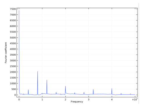
Frequency content of the power deposition into a dual frequency capacitively coupled plasma. The power deposition occurs at multiple different frequencies indicating a complex mechanism of power transfer from the fields to the electrons.
Microwave Plasmas
Microwave plasmas, or wave heated discharges, are sustained when electrons can gain enough energy from an electromagnetic wave as it penetrates into the plasma. The physics of a microwave plasma is quite different depending on whether the TE mode (out-of-plane electric field) or the TM mode (in-plane electric field) is propagating. In the 2D axisymmetric case, the TE mode means that only the azimuthal component of the electric field is computed and the TM mode means that the in-plane, r and z components of the electric field are computed. In both cases it is not possible for the electromagnetic wave to penetrate into regions of the plasma where the electron density exceeds the critical electron density (around 7.6x10¹⁶ 1/m3 for argon at 2.45 GHz). On this contour corresponding to the critical electron density, the wave goes from being propagating to evanescent. This means that all the power from the wave is absorbed in a very small region in space, which can make the model numerically unstable. The pressure range for microwave plasmas is very broad. For electron cyclotron resonance (ECR) plasmas, the pressure can be on the order of 1 Pa or less. For non-ECR plasmas the pressure typically ranges from 100 Pa up to atmospheric pressure. The power can range from a few watts all the way up to several kilowatts. Microwave plasmas are popular due to the cheap availability of microwave power.
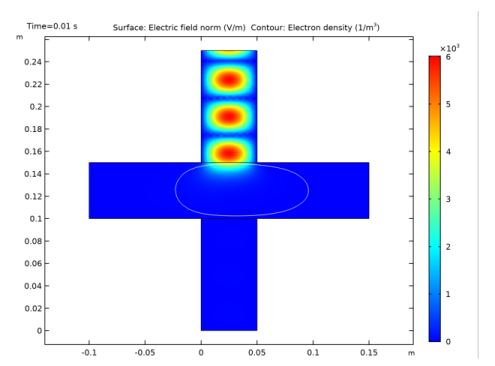
Electric field (surface) and critical electron density (white contour) in a cross-configuration microwave plasma.
Plasma-enhanced Chemical Vapor Deposition
Plasma-enhanced chemical vapor deposition (PECVD) is a discharge operating in a reactive gas. It is used as an alternative to traditional chemical vapor deposition, since it can generate the radical species required to initiate the deposition process very efficiently, without the need for very high gas temperatures. In the case of silicon deposition in a silane plasma, the electron impact reactions can dissociate the silane into highly reactive silicon hydrides and hydrogen gas. Equally as important as the gas phase reactions is the complicated set of chemical reactions that take place on the surface of the wafer. Typical PECVD reactors are inductively coupled plasmas, but microwave discharges can also be used.
PECVD model of silicon deposition onto a wafer (surface) from a silane plasma. Silane is fed in from the shower head at the top and broken into radical species due to the presence of the electrons, which are sustained through induction heating.
Dielectric Barrier Discharges
Dielectric barrier discharges (DBD) have many uses including light generation for plasma and LCD displays, ozone generation, and surface modification. The operating principle for a dielectric barrier discharge is as follows: there is a small gap filled with a gas in between two dielectric plates. The gap between the two dielectric plates is typically less than one millimeter. On one of the dielectric plates, a sinusoidal voltage is applied. The other plate is electrically grounded. As the voltage applied to the top plate increases, the electric field increases in the gap between the plates. Any free electrons in the gap will be accelerated and if the electric field is strong enough they may acquire enough energy to cause ionization. This can lead to a cascade effect where the number of electrons in the gap increases exponentially on a nanosecond time scale. Electrons created via electron impact ionization rush toward one of the dielectric plates, in the opposite direction to the electric field. An equal number of ions are also generated during electron impact ionization (electrons and ions must be created in equal pairs to preserve the overall charge balance). The ions rush toward the opposite dielectric plate in the same direction as the electric field. As a result, surface charge with opposite sign accumulates on both dielectric plates. This causes the electric field to become shielded from the gas filled gap. In fact, the electric field across the gap cannot exceed the breakdown electric field, which is highly dependent on the gas and background pressure. The breakdown electric field is also a function of the surface properties of the dielectric material. Surface charge accumulation temporarily terminates the discharge until the field reverses direction and the process repeats in the opposing direction.
Dielectric Barrier Discharge: Plot of the mass fraction of electronically excited argon atoms in a dielectric barrier discharge. The x-axis represents space and the y-axis time. The applied frequency is 10 kHz.
Dielectric barrier discharges typically operate in the pressure range of 0.1–3 atm with an applied voltage of 1–100 kV and a frequency of kHz up to MHz. The dielectric barriers are usually made or quartz, glass, or a ceramic material. Electrode spacing is typically small, ranging from 100 μm up to several mm.
Space Thrusters and Magnetron Sputtering
Magnetrons and space thrusters are essentially DC discharges aided by a static magnetic field. When the pressure is low enough (less than around 1 Pa), the magnetic field can trap the electrons so they are confined by the magnetic field lines, rather than escape to the walls. The trapping of the electrons results in more ionization collisions with the background gas and higher plasma densities than would normally be expected at such low pressures. Typical applied voltages are on the order of 500 V resulting in plasma currents on the order of amperes. The magnetic flux density is typically on the order of 0.01–0.15 T. Modeling low-pressure magnetized DC discharges is very challenging, indeed most practical applications are beyond the current capabilities of the Plasma Module; see Limitations of the Plasma Module below.
Equilibrium Discharges
Equilibrium discharges (sometimes called thermal plasmas) have a large range of industrial applications including: cutting, welding, spraying, waste destruction and surface treatment. Thermal plasmas are assumed to be under partial to complete local thermodynamic equilibrium (LTE) conditions. Under LTE, the plasma can be considered a conductive fluid mixture and therefore, be modeled using the magnetohydrodynamics (MHD) equations. The electron temperature is assumed to be equal to the temperature of the background gas. Equilibrium discharges are treated differently to the other examples above. The chemical composition of the plasma is not computed, only the gas temperature and electric fields. Sometimes the background velocity and pressure of the gas is also computed. These models allow the thermal loads on surfaces to be computed in a more efficient and stable way than using a non-equilibrium discharge model.