T-Junction
Use the T-Junction node to specify additional energy losses due to irreversible turbulent friction in a T-junction, which can act as a split or a merger.
Selection Settings
Figure 2-1: A T-junction with local pressure indications.
The T-junction is intended for a point that is connected to exactly two collinear main branches and one perpendicular side branch. If this condition is not met, a warning message will be issued when solving. The flow can go in either direction through each of the main branches and the side branch. See Figure 2-1.
The automatic search for T-junction points is possible. If you want to use this option, clear the Manual control of selections check box, the selections will be replaced by the automatic ones. If you want to modify the selection, select Manual control of selections again.
Friction Specification
Several options to specify pressure drop across the junction branches are available.
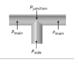
The Loss coefficients option allows you to enter a value or expression for the Loss coefficient main branch Kmain for the energy loss between main branch and junction (the default is 0.1) and the Loss coefficient side branch Kside for the energy loss between the side branch and junction (the default is 1.2). Both are dimensionless numbers. See Figure 2-1.
The respective losses are calculated as
.
For Nonisothermal Pipe Flow and Reacting Pipe Flow interface interfaces, the respective pressure drops are calculated as
.
The advantage of using loss coefficients is that they are readily available in engineering tables and textbooks.
The Loss coefficients, extended model option is available for the Pipe Flow interface. This option allows you to specify the loss coefficient in more details and account for the flow directions. Enter values or expressions for the six dimensionless loss coefficients. See Figure 2-2.
Figure 2-2: T-junction, joining and separating flows.
The losses for the outgoing branches are calculated as
The total pressure is assume to be equal for all incoming branches:
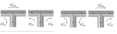
Use the Pressure drops option to specify a value or expression for the pressure drop explicitly for each branch respectively:
Main 1 is the main pipe segment that has the lower index of the two in the selection list (for example, see the list in Pipe Properties).
Advanced Settings
The angle tolerance is used to specify the tolerance to a geometry not being a perfect T. Increase the tolerance if you get an error message but accept the geometry even if does not fulfill the requirements for an Y-shape.
Constraint Settings
To display this section, click the Show More Options button () and select Advanced Physics Options.