PDF

Iron Sphere in a 13.56 MHz Magnetic Field
Introduction
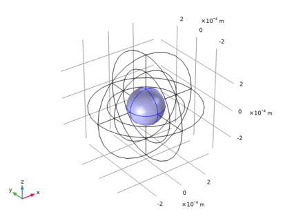
An iron sphere is exposed to a spatially uniform, sinusoidally time-varying, background magnetic field. The frequency of the field is so high that the skin depth in the sphere is much smaller than the radius. At such high frequencies it is possible to model only the fields and induced currents on the surface of the sphere, thus avoiding the need for solving for the fields within the volume of the sphere, resulting in significantly reduced model size.
Figure 1: An iron sphere is exposed to a spatially uniform, sinusoidally time-varying, background magnetic field.
Model Definition
Figure 1 shows the setup, with an iron sphere placed in a spatially uniform time-harmonic background magnetic field. The background field is applied using the Reduced field formulation available in the Magnetic Fields interface. The model space is truncated by an Infinite Elements region, a domain condition approximating a domain that extends to infinity. When using Infinite Element Domain features, the boundary condition on the outside of the modeling domain only marginally affects the solution, since it is placed at a large physical distance.
At 13.56 MHz the skin depth of iron is ~0.65 μm. The surrounding air has εr = 1, μr = 1, and σ = 0 S/m, which implies an infinite skin depth. To improve the stability of the solver, the application uses a small but nonzero artificial conductivity in the air (σ = 0.1 S/m).
Because the skin depth in the iron sphere is much smaller than the sphere radius, it is possible to assume that the induced currents flow only in a thin surface layer with negligible thickness. This phenomenon can be modeled using the Impedance Boundary Condition on the iron sphere surface. The inside of the iron sphere is not modeled at all, since it is assumed that there are no significant currents, and negligible fields, within the sphere.
The interior of the sphere is explicitly removed from the geometry by means of a Delete operation. An alternative approach is to modify the selection of the Magnetic Fields interface to exclude the interior of the sphere, without deleting the corresponding geometrical domain. This second solution can be useful for example in multiphysics applications when another physics interface (such as Heat Transfer) must be solved in the core as well.
Results and Discussion
Figure 2 plots the magnetic field and the induced current density along with a visualization of the mesh at the sphere surface.
Figure 2: The induced currents on the surface of the iron sphere and the magnetic field in the surrounding space.
Application Library path: ACDC_Module/Tutorials/iron_sphere_13mhz_bfield
Modeling Instructions
From the File menu, choose New.
New
In the New window, click Model Wizard.
Model Wizard
1
In the Model Wizard window, click 3D.
2
In the Select Physics tree, select AC/DC>Electromagnetic Fields>Magnetic Fields (mf).
3
Click Add.
4
Click Study.
5
In the Select Study tree, select General Studies>Frequency Domain.
6
Click Done.
Global Definitions
Define a few parameters to be used in the model setup.
Parameters 1
1
In the Model Builder window, under Global Definitions click Parameters 1.
2
In the Settings window for Parameters, locate the Parameters section.
3
Geometry 1
Sphere 1 (sph1)
Create a sphere with two layers plus an inner core. The outermost layer represents the exterior air region, scaled using the Infinite Element Domain, the middle layer is the unscaled air domain, and the core represents the iron sphere.
1
In the Geometry toolbar, click Sphere.
2
In the Settings window for Sphere, locate the Size section.
3
In the Radius text field, type 3*r0.
4
Click to expand the Layers section. In the table, enter the following settings:
Remove the core domain from the model domain.
Delete Entities 1 (del1)
1
In the Model Builder window, right-click Geometry 1 and choose Delete Entities.
2
Click the Wireframe Rendering button in the Graphics toolbar.
3
In the Settings window for Delete Entities, locate the Entities or Objects to Delete section.
4
From the Geometric entity level list, choose Domain.
5
On the object sph1, select Domain 9 only.
6
Click Build All Objects.
The surface of the iron sphere is now an exterior boundary and it is now possible to apply the Impedance boundary condition.
Definitions
Create a set of selections before setting up the physics. First, create a selection for the surface of the iron sphere.
Explicit 1
1
In the Definitions toolbar, click Explicit.
2
In the Settings window for Explicit, locate the Input Entities section.
3
From the Geometric entity level list, choose Boundary.
4
The simplest way to do this is to select the Group by continuous tangent check box, then click on any boundary on the surface of the iron sphere.
5
Right-click Explicit 1 and choose Rename.
6
In the Rename Explicit dialog box, type Iron surface in the New label text field.
7
Add an Infinite Element Domain on the outermost layer of the model domain.
Infinite Element Domain 1 (ie1)
1
In the Definitions toolbar, click Infinite Element Domain.
2
3
In the Settings window for Infinite Element Domain, locate the Geometry section.
4
From the Type list, choose Spherical.
Magnetic Fields (mf)
Set up the physics interface to apply a uniform background magnetic fields. In the Magnetic Fields interface, the background field must be specified in terms of a vector potential field.
1
In the Model Builder window, under Component 1 (comp1) click Magnetic Fields (mf).
2
In the Settings window for Magnetic Fields, locate the Background Field section.
3
From the Solve for list, choose Reduced field.
4
Specify the Ab vector as
Impedance Boundary Condition 1
1
In the Physics toolbar, click Boundaries and choose Impedance Boundary Condition.
2
In the Settings window for Impedance Boundary Condition, locate the Boundary Selection section.
3
From the Selection list, choose Iron surface.
Materials
Assign the material properties. First, use air for all domains.
Add Material
1
In the Home toolbar, click Add Material to open the Add Material window.
2
Go to the Add Material window.
3
4
Click Add to Component in the window toolbar.
Materials
Air (mat1)
Specify the conductivity of the air to a small value in order to improve the convergence rate.
1
In the Settings window for Material, locate the Material Contents section.
2
Override the core sphere surface with iron.
Add Material
1
Go to the Add Material window.
2
In the tree, select Built-in>Iron.
3
Click Add to Component in the window toolbar.
4
In the Home toolbar, click Add Material to close the Add Material window.
Materials
Iron (mat2)
1
In the Settings window for Material, locate the Geometric Entity Selection section.
2
From the Geometric entity level list, choose Boundary.
3
From the Selection list, choose Iron surface.
Mesh 1
Specify an extra fine mesh on the surface of the iron sphere.
Size
In the Model Builder window, under Component 1 (comp1) right-click Mesh 1 and choose Edit Physics-Induced Sequence.
Size 1
1
In the Model Builder window, right-click Free Tetrahedral 1 and choose Size.
2
In the Settings window for Size, locate the Geometric Entity Selection section.
3
From the Geometric entity level list, choose Boundary.
4
From the Selection list, choose Iron surface.
5
Locate the Element Size section. From the Predefined list, choose Extra fine.
6
Click Build All.
Plot the meshed structure to review the quality of the mesh.
7
In the Mesh toolbar, click Plot.
Results
Mesh 1
By default, the boundary mesh is plotted, so only the triangular elements on the outer boundaries are visible. Perform the following operations to inspect the tetrahedral elements in the interior of the geometry.
1
In the Settings window for Mesh, locate the Color section.
2
From the Element color list, choose Yellow.
3
Click to expand the Element Filter section. Select the Enable filter check box.
4
In the Expression text field, type z<0 to plot a section of the mesh.
5
In the 3D Plot Group 1 toolbar, click Plot.
As it is apparent from the plot, no mesh is generated in the core since it was removed from the geometry.
Study 1
Step 1: Frequency Domain
1
In the Model Builder window, under Study 1 click Step 1: Frequency Domain.
2
In the Settings window for Frequency Domain, locate the Study Settings section.
3
In the Frequencies text field, type 13.56[MHz].
4
In the Model Builder window, click Study 1.
5
In the Settings window for Study, locate the Study Settings section.
6
Clear the Generate default plots check box.
7
In the Home toolbar, click Compute.
Results
Selection
Add a selection to the data set to plot quantities on the surface of the iron sphere.
1
In the Model Builder window, expand the Results>Datasets node.
2
Right-click Study 1/Solution 1 (sol1) and choose Selection.
3
In the Settings window for Selection, locate the Geometric Entity Selection section.
4
From the Geometric entity level list, choose Boundary.
5
From the Selection list, choose Iron surface.
6
Select the Propagate to lower dimensions check box.
Create surface plots for the surface current density norm and the mesh on the iron sphere.
3D Plot Group 2
1
In the Home toolbar, click Add Plot Group and choose 3D Plot Group.
2
In the Settings window for 3D Plot Group, type Surface Current Density (mf) in the Label text field.
Surface 1
1
Right-click Surface Current Density (mf) and choose Surface.
2
In the Settings window for Surface, click Replace Expression in the upper-right corner of the Expression section. From the menu, choose Component 1>Magnetic Fields>Currents and charge>mf.normJs - Surface current density norm - A/m.
3
Locate the Coloring and Style section. From the Color table list, choose GrayPrint.
4
Clear the Color legend check box.
5
Select the Reverse color table check box.
Surface 2
1
Right-click Surface 1 and choose Duplicate.
2
In the Settings window for Surface, locate the Coloring and Style section.
3
From the Coloring list, choose Uniform.
4
From the Color list, choose Black.
5
Select the Wireframe check box.
Surface Current Density (mf)
Add an arrow surface plot for the surface current density and an arrow volume plot showing the magnetic flux density.
Arrow Surface 1
1
In the Model Builder window, right-click Surface Current Density (mf) and choose Arrow Surface.
2
In the Settings window for Arrow Surface, click Replace Expression in the upper-right corner of the Expression section. From the menu, choose Component 1>Magnetic Fields>Currents and charge>mf.Jsx,...,mf.Jsz - Surface current density.
3
Locate the Coloring and Style section. From the Arrow type list, choose Cone.
4
Select the Scale factor check box.
5
6
Locate the Arrow Positioning section. From the Placement list, choose Mesh nodes.
Color Expression 1
1
Right-click Arrow Surface 1 and choose Color Expression.
2
In the Settings window for Color Expression, click Replace Expression in the upper-right corner of the Expression section. From the menu, choose Component 1>Magnetic Fields>Currents and charge>mf.normJs - Surface current density norm - A/m.
3
Locate the Coloring and Style section. From the Color table list, choose ThermalLight.
4
Clear the Color legend check box.
Arrow Volume 1
1
In the Model Builder window, right-click Surface Current Density (mf) and choose Arrow Volume.
2
In the Arrow Positioning section, specify the grid points according to the following table:
Color Expression 1
1
In the Model Builder window, right-click Arrow Volume 1 and choose Color Expression.
The default settings color the arrows according to the local magnetic flux density norm.
Compare the resulting plot with that in Figure 2.