PDF

Force Calculation 1 — Introduction
Force Verification Series Overview
This force verification series investigates the accuracy and general numerical behavior of electromagnetic force calculations when using COMSOL Multiphysics® and the AC/DC Module. Employing various techniques, the total force and torque on a rigid body is determined and compared to analytical models. The quality of the computed Maxwell surface stress tensor is investigated.
A great increase in accuracy is achieved by applying fillets, advanced meshing and auxiliary force-probe surfaces. Using the Magnetic Fields, No Currents and Magnetic Fields, No Currents, Boundary Elements interfaces, the boundary element method (BEM) and the finite element method (FEM) are compared for several mesh sizes. A parametric sweep is used to investigate mesh convergence for both BEM and FEM.
The following tutorials are included in this series:
Force Calculation 2 — Magnetic Force BEM FEM
Figure 1: The Maxwell surface stress tensor at the magnet pole for the force verification case, when using the boundary element method and a mesh scaling factor of one half.
This verification model treats the case of two parallel magnetized rods of one meter length, placed one meter apart. The relative permeability is assumed to be one everywhere. The remanent flux density Br inside the rods is chosen such that the analytical model predicts a repelling force between the two rods, of one Newton exactly.
Force Calculation 3 — Magnetic Torque BEM FEM
Figure 2: The Maxwell surface stress tensor at the magnet pole for the torque verification case, when using the boundary element method and a mesh scaling factor of one half.
This model is a continuation of the Magnetic Force BEM FEM verification model. A single magnetized rod of one meter length, is placed in a perpendicular external field Be. The relative permeability is assumed to be one everywhere. The strength of the external field is chosen such that the analytical model predicts a torque on the rod, of one Newton-meter exactly.
Model Definition (Introduction Tutorial)
This model serves as a basis for subsequent tutorials in this series (the Magnetic Force BEM FEM, and Magnetic Torque BEM FEM tutorials). It provides the geometries used in this series (see Figure 3), along with detailed modeling instructions for building them (see sections Modeling Instructions — Magnetic Force Verification Geometry and Modeling Instructions — Magnetic Torque Verification Geometry respectively).
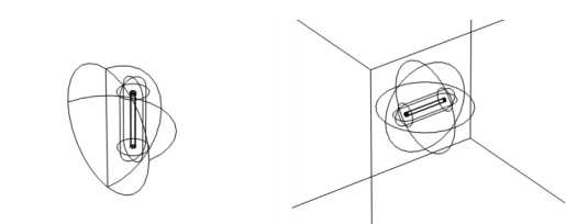
Figure 3: The geometry used for force verification (left), and torque verification (right).
The force verification geometry consists of a single rod1 inside a semisphere. The semisphere will represent the boundary between the Magnetic Fields, No Currents interface, and the Magnetic Fields, No Currents, Boundary Elements interface.
The torque verification geometry consists of a single rod in a spherical domain, encapsulated by a cubic surface. The sphere represents the boundary between the Magnetic Fields, No Currents interface, and the Magnetic Fields, No Currents, Boundary Elements interface. The cube will be used to apply the external field.
Experienced users with little or no interest in geometry building, may choose to skip this part and continue with one of the aforementioned tutorials. When you are new to COMSOL however, or new to this series, it is worthwhile to take some time for this, as it will help you get familiar with the basics.
Application Library path: ACDC_Module/Verification,_Forces/force_calculation_01_introduction
Modeling Instructions (Introduction Tutorial)
From the File menu, choose New.
New
In the New window, click Model Wizard.
Model Wizard
1
In the Model Wizard window, click 3D.
In this case, we will not select any Physics. This will be done in subsequent tutorials, depending on the analysis performed.
2
Click Done.
Global Definitions
The geometries in this verification series are based on parameters. This is not strictly necessary in COMSOL, rather it accommodates quick adjustments and helps keeping things consistent.
Parameters 1
1
In the Model Builder window, under Global Definitions click Parameters 1.
2
In the Settings window for Parameters, locate the Parameters section.
3
Click Load from File.
4
The parameter Rd is used to set the distance between a magnetized rod and its mirror image. It is relevant for the Magnetic Force BEM FEM verification model. The parameter Ra sets the angle at which a single magnetized rod is oriented with respect to a uniform external field, as discussed in the Magnetic Torque BEM FEM verification model.
Modeling Instructions — Magnetic Force Verification Geometry
Geometry 1
1
In the Model Builder window, under Component 1 (comp1) click Geometry 1.
2
In the Settings window for Geometry, type Geometry 1 (Magnetic Force Verification) in the Label text field.
The first geometry is used for force verification. Although the model considers two rods, the geometry contains only one of them. The second rod is included later, by means of a symmetry condition in the physics. The rod and its accompanying force probe surface are created by means of a revolved work plane.
Start by building the axisymmetric cross section of the rod in the work plane.
Work Plane 1 (wp1)
1
In the Geometry toolbar, click Work Plane.
2
In the Settings window for Work Plane, locate the Plane Definition section.
3
From the Plane list, choose xz-plane.
Plane Geometry
In the Model Builder window, click Plane Geometry.
Work Plane 1 (wp1)>Rectangle 1 (r1)
1
In the Work Plane toolbar, click Rectangle.
2
In the Settings window for Rectangle, locate the Size and Shape section.
3
In the Width text field, type Rr.
4
In the Height text field, type Rl.
5
Locate the Position section. In the yw text field, type -Rl/2.
6
Click to expand the Layers section. In the table, enter the following settings:
7
Clear the Layers on bottom check box.
8
Select the Layers on top check box.
9
In the Work Plane toolbar, click Build All.
10
Click the Zoom Extents button in the Graphics toolbar.
Work Plane 1 (wp1)>Fillet 1 (fil1)
1
In the Work Plane toolbar, click Fillet.
2
In the Settings window for Fillet, locate the Radius section.
3
In the Radius text field, type Rrf.
4
On the object r1, select Points 4 and 6 only.
5
In the Work Plane toolbar, click Build All.
The fillet is a crucial part of the geometry. Without it the fields will reach a singularity at the sharp corner, making the force calculations less accurate (feel free to investigate this later).
Work Plane 1 (wp1)>Rectangle 2 (r2)
1
In the Work Plane toolbar, click Rectangle.
2
In the Settings window for Rectangle, locate the Size and Shape section.
3
In the Width text field, type 5*Rr.
4
In the Height text field, type Rl+10*Rr.
5
Locate the Position section. In the yw text field, type -(Rl+10*Rr)/2.
6
In the Work Plane toolbar, click Build All.
7
Click the Zoom Extents button in the Graphics toolbar.
Work Plane 1 (wp1)>Fillet 2 (fil2)
1
In the Work Plane toolbar, click Fillet.
2
In the Settings window for Fillet, locate the Radius section.
3
In the Radius text field, type 5*Rr.
4
On the object r2, select Points 2 and 3 only.
5
In the Work Plane toolbar, click Build All.
Now that the axisymmetric cross section is complete, proceed by revolving it into a 3D geometry.
6
In the Model Builder window, click Geometry 1 (Magnetic Force Verification).
Revolve 1 (rev1)
1
In the Geometry toolbar, click Revolve.
2
In the Settings window for Revolve, locate the Revolution Angles section.
3
Clear the Keep original faces check box.
4
Click Build All Objects.
5
Click the Wireframe Rendering button in the Graphics toolbar.
6
Click the Zoom Extents button in the Graphics toolbar.
So far, the geometry has been built around the coordinate system’s origin. Since the symmetry plane will be located at x = 0, the rod will have to be displaced by Rd/2 meters in the positive x-direction. Notice that the parameter Rd allows you to change the distance between the rods (feel free to investigate the computed force as a function of Rd later).
Move 1 (mov1)
1
In the Geometry toolbar, click Transforms and choose Move.
2
3
In the Settings window for Move, locate the Displacement section.
4
In the x text field, type Rd/2.
5
Click Build All Objects.
The next work plane is used to build a semisphere. In the Magnetic Force BEM FEM verification model, this semisphere will represent the boundary between the Magnetic Fields, No Currents interface, and the Magnetic Fields, No Currents, Boundary Elements 2 interface.
Work Plane 2 (wp2)
1
In the Geometry toolbar, click Work Plane.
2
In the Settings window for Work Plane, locate the Plane Definition section.
3
From the Plane list, choose yz-plane.
Plane Geometry
In the Model Builder window, click Plane Geometry.
Work Plane 2 (wp2)>Circle 1 (c1)
1
In the Work Plane toolbar, click Circle.
2
In the Settings window for Circle, locate the Size and Shape section.
3
In the Radius text field, type 1.5*sqrt((Rl/2)^2+(Rd/2)^2).
This is actually 1.5 times the distance between one of the rod’s poles and the origin. Notice that for longer expressions like this one, the easiest way to go, is to copy-paste them directly from this *.pdf file to COMSOL.
4
In the Sector angle text field, type 180.
5
Locate the Rotation Angle section. In the Rotation text field, type 90.
6
In the Work Plane toolbar, click Build All.
7
Click the Zoom Extents button in the Graphics toolbar.
8
In the Model Builder window, click Geometry 1 (Magnetic Force Verification).
Revolve 2 (rev2)
1
In the Geometry toolbar, click Revolve.
2
In the Settings window for Revolve, locate the Revolution Angles section.
3
Click the Angles button.
4
In the End angle text field, type 180.
5
Click Build All Objects.
6
Click the Zoom Extents button in the Graphics toolbar.
You have now completed the geometry used for the force verification model. You can save the resulting file, so that you can use it as a basis for the second geometry.
7
From the File menu, choose Save As.
8
Browse to a suitable folder and type the file name force_calculation_01_introduction.mph.
Modeling Instructions — Magnetic Torque Verification Geometry
The second geometry is used for torque verification. It contains a single rod in a spherical domain, encapsulated by a cubic surface. The cube will be used to apply an external field. Since the geometry is similar to the one used for force verification, we reuse the sequence from that one and make some modifications.
Start by adding a new model component.
Add Component
In the Model Builder window, right-click the root node and choose Add Component>3D.
Geometry 2
1
In the Settings window for Geometry, type Geometry 2 (Magnetic Torque Verification) in the Label text field.
2
In the Geometry toolbar, click Insert Sequence.
3
4
In the Home toolbar, click Build All.
5
Click the Wireframe Rendering button in the Graphics toolbar.
6
Click the Zoom Extents button in the Graphics toolbar.
This effectively copies the geometry sequence from Component 1, to Component 2.
Next, delete those parts of the sequence that are related to the force verification geometry in particular.
Revolve 2 (rev2), Work Plane 2 (wp2), Move 1 (mov1)
1
In the Model Builder window, right-click Revolve 2 (rev2) and choose Delete.
2
Repeat these steps for Work Plane 2 (wp2), and Move 1 (mov1).
3
In the Home toolbar, click Build All.
4
Click the Zoom Extents button in the Graphics toolbar.
The resulting geometry has been built with the rod oriented vertically. Since the external field will be pointing in the z-direction, the rod will have to be rotated by Ra degrees. Notice that the parameter Ra allows you to change the angle of the rod with respect to the external field (feel free to investigate the computed torque as a function of Ra later).
Rotate 1 (rot1)
1
In the Geometry toolbar, click Transforms and choose Rotate.
2
3
In the Settings window for Rotate, locate the Rotation section.
4
In the Angle text field, type Ra.
5
From the Axis type list, choose y-axis.
6
Click Build All Objects.
7
Click the Zoom Extents button in the Graphics toolbar.
Next will be a sherical domain and a cubic surface. In the Magnetic Torque BEM FEM verification model, the sphere will represent the boundary between the Magnetic Fields, No Currents interface, and the Magnetic Fields, No Currents, Boundary Elements 2 interface.
Sphere 1 (sph1)
1
In the Geometry toolbar, click Sphere.
2
In the Settings window for Sphere, locate the Size section.
3
In the Radius text field, type Rl.
4
Click Build All Objects.
5
Click the Zoom Extents button in the Graphics toolbar.
Block 1 (blk1)
1
In the Geometry toolbar, click Block.
2
In the Settings window for Block, locate the Object Type section.
3
From the Type list, choose Surface (this setting is important for the model to work properly, its implications will become apparent in subsequent tutorials).
4
Locate the Size and Shape section. In the Width text field, type Cs.
5
In the Depth text field, type Cs.
6
In the Height text field, type Cs.
7
Locate the Position section. From the Base list, choose Center.
8
Click Build All Objects.
9
Click the Zoom Extents button in the Graphics toolbar.
You have now completed the geometry used for the torque verification model. The result is a COMSOL file containing two geometries. These will serve as a basis for several models investigating the accuracy of force and torque computations for different methods and formulations. Subsequent tutorials will refer to this file, as force calculation 01 introduction.mph.
The next tutorial in this series will investigate the performance of the boundary element method (BEM) and the finite element method (FEM) within the context of force calculations.
 

1
The model itself considers two rods actually; the second rod will be included by means of a symmetry condition in the physics.