Theory for Rack and Pinion
The rack and pinion node connects a spur or helical rack with a spur or helical gear in such a way that at the contact point they have no relative motion along the line of action. The remaining displacements and rotations of the rack and gear are independent of each other.
For a line contact model, one additional constraint is added to restrict the relative rotation about a line joining the rack and gear centers. When friction is included on a rack and pinion node, frictional forces in the plane perpendicular to the line of action are added on the rack and pinion.
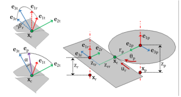
Figure 3-16: The sketch of a rack and pinion pair where line of action is computed by the clockwise rotation of the tangent.
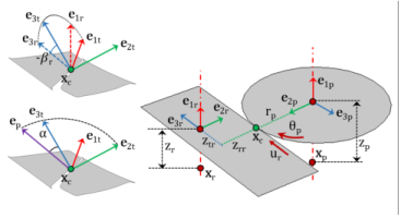
The degrees of freedom at the rack and pinion are urk and θpn. They are defined as the displacement of the rack along the third axis and the rotation of the pinion about the first axis of their respective local coordinate system, respectively.
Figure 3-17: The sketch of a rack and pinion pair where line of action is computed by the counterclockwise rotation of the tangent.
Gear Pair Compatibility Criteria
Normal Pitch
The normal pitch of the rack and pinion must be same.
Gear Local Coordinate System
Initial Local Coordinate System
The third axis for the rack () and the first axis of the pinion () is the input on the respective nodes. In 2D, the first axis of the rack and pinion are assumed to be the out-of-plane direction.
The second axis is defined as follows:
The first axis of rack and the third axis of pinion are defined as follows:
Contact Point Position and Offset
Contact Point Position
The point of contact (xcp) on a rack in its local coordinate system can be defined as:
where zr,rk and zt,rk are the contact point offset from the center of rotation in the radial and tangential direction, respectively.
In 2D, the expression for the position of contact point reduces to:
Contact Point Offset
The contact point offset from the pinion center (zpn) is the input.
The contact point offset from the rack center in the axial direction (zrk) is defined as:
The contact point offset from the rack center in the radial direction (zr,rk) is defined as:
The contact point offset from the rack center in the tangential direction (zt,rk) is defined as:
In 2D, the expression reduces to:
Gear Pair Constraints
Translation-Rotation constraint
This constraint relates the pinion rotation with the rack displacement: