The Thermal Contact feature node has correlations to evaluate the joint conductance at two contacting surfaces.
The heat fluxes at the upside and downside boundaries depend on the temperature difference according to the relations:
The joint conductance h has three contributions: the constriction conductance,
hc, from the contact spots, the gap conductance,
hg, due to the fluid at the interstitial space, and the radiative conductance,
hr:
Here, Hc is the microhardness of the softer material,
p is the contact pressure, and
kcontact is the harmonic mean of the contacting surface conductivities:
The relative pressure p ⁄ Hc can be evaluated by specifying
Hc directly or using the following relation (4.16.1 in
Ref. 1) for the relative pressure using
c1 and
c2, the Vickers correlation coefficient and size index:
The coefficients c1 and
c2 are the Vickers correlation coefficient and size index, respectively, and
σ0 is equal to 1 µm. For materials with Brinell hardness between 1.30 and 7.60 GPa,
c1 and
c2 are given by the correlation below (4.16.1 in
Ref. 1):
Here, Econtact is an effective Young’s modulus for the contact interface, satisfying (4.16.3 in
Ref. 1):
where Eu and
Ed are the Young’s moduli of the two contacting surfaces and
νu and
νd are the Poisson’s ratios.
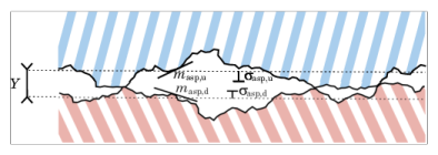
Here kg is the gas conductivity,
Y denotes the mean separation thickness (see
Figure 4-21), and
Mg is the gas parameter equal to:
In these relations, α is the contact thermal accommodation parameter,
β is a gas property parameter (equal to 1.7 for air),
Λ is the gas mean free path,
kB is the Boltzmann constant,
D is the average gas particle diameter,
pg is the gas pressure (often the atmospheric pressure), and
Tg is the gap temperature equal to:
The mean separation thickness, Y, is a function of the contact pressure,
p. For low values of
p near 0 Pa,
Y goes to infinity since no contact occur. For high values of
p — greater than
Hc ⁄2 in the Cooper-Mikic-Yovanovich model and greater than
Hc ⁄4 in the Mikic elastic model —
Y reduces to 0 meaning that the contact is considered as perfect.
The friction heat, Qb, is partitioned into
rQb and
(1 − r)Qb at the contact interface. If the two bodies are identical,
r and
(1 − r) would be 0.5 so that half of the friction heat goes to each surface. However, in the general case where the two bodies are made of different materials, the partition rate might not be 0.5. The Charron’s relation (
Ref. 2) defines
r as: