By analogy with Ohm’s law for electric current, the heat rate P (SI unit: W) in a material due to the temperature difference
ΔT (SI unit: K) is
where R (SI unit: K/W) is the thermal resistance.
When considering steady conduction through a plane shell of surface area A (SI unit: m²), thickness
L (SI unit: m), and constant thermal conductivity
k (SI unit: W/(m·K)), the thermal resistance
R is:
When considering steady conduction through a cylindrical shell of inner radius ri and outer radius
ro (SI unit: m), height
H (SI unit: m), and constant thermal conductivity
k (SI unit: W/(m·K)), the thermal resistance
R is:
When considering steady conduction through a spherical shell of inner radius ri and outer radius
ro (SI unit: m), and constant thermal conductivity
k (SI unit: W/(m·K)), the thermal resistance
R is:
When considering several materials, Equation 4-69 can be updated to get a relationship between the heat transfer rate
P and the overall temperature difference
ΔToverall (SI unit: K):
where Rtot (SI unit: K/W) is the total thermal resistance.
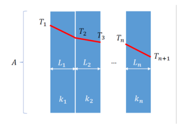
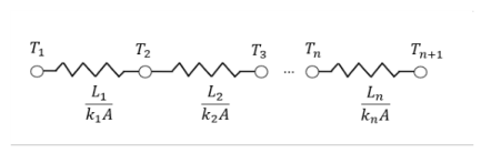
When considering steady conduction through a composite wall made of n layers of thermal resistances
R1,...,
Rn, see
Figure 4-6, the total resistance is defined by:
where ΔToverall = Tn+1 − T1. Note that by analogy with electrical circuits, the elements placed in series in the circuit share the heat rate (flow variable).
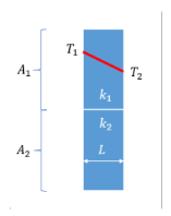
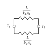
When considering steady conduction through a composite wall made of n slabs of thermal resistances
R1,…,
Rn, see
Figure 4-7, the total resistance is defined by:
where ΔToverall = T2 − T1. Note that by analogy with electrical circuits, the elements placed in parallel in the circuit share the temperature difference (effort variable).
See Equivalent Thermal Conductivity Correlations for details about the correlations used to modify the thermal conductivity to account for convective heat flux.
See Rosseland Approximation Theory for details about how to modify the thermal conductivity to account for radiative heat flux when the optical thickness of the medium is large.