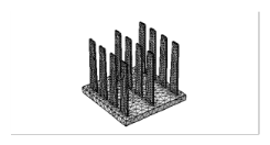
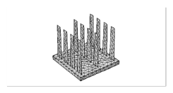
When the thickness of the fins is small in the x direction, the fins can be defined as boundaries instead of solids in order to reduce the size of the model. Indeed, small elements are required to mesh the fins across their thickness in this case. It is done by setting the
shell parameter to 1. The default meshes obtained with
shell = 0 (left) and
shell=1 (right) are shown in
Table 3-14 for an example configuration. Setting
shell to 1 significantly reduces the number of mesh elements, as shown below.
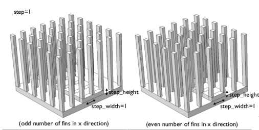
A step can be defined in the x direction at the center on the base. The parameter
step_width specifies the number of filled gaps from middle to border by the step, as shown on
Figure 3-16. This option is not available for shell fins (
shell=1).