Heat Part Library Contents
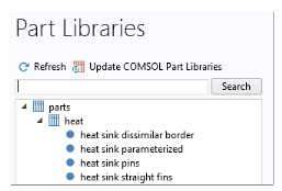
The part library included with the Heat Transfer Module contains typical heat sink geometries. When accessing the library, the parts are sorted as in the figure below:
The heat sinks are composed of a rectangular base and an array of pin or straight fins, as shown on Figure 3-14.
Figure 3-14: Heat sinks components
All entities are fully parameterized, making them easy to use as parts in industrial models where heat sinks are used for cooling. For example, you can control the number, the shape, the dimensions, and the placement of the fins on the base. In addition, fillet, chamfer, and notch transformations can be applied to the fins, and parameter checks are applied to ensure that the values set in the Input Parameters section are valid. Finally, the fins can be defined as solids or as boundaries for computational efficiency.
The library includes four parts. The Heat Sink — Parameterized Fin Types part is the most general part. It supports multiple parameterization, while a reduced number of parameters is available in the three other parts, as shown in Table 3-13.
In the Heat Sink — Pin Fins part, all the fins are pins with the same dimension, whereas the outer and inner fins (in the y direction) can have distinct dimensions in the Heat Sink — Dissimilar Border Pins part. You may use the Heat Sink — Straight Fins part to define a heat sink made of only straight fins.
By default, the base of the heat sink is positioned at the origin of the xy-plane. You can apply a Displacement and a Rotation to this configuration in the Position and Orientation of Output section.
Finally, each fin is a separate domain and can be easily deleted, and selections can be defined, for example for the base bottom face (Boundary Selections section) or the array of fins (Domain Selections section).