The Heat Transfer Module Physics Interfaces
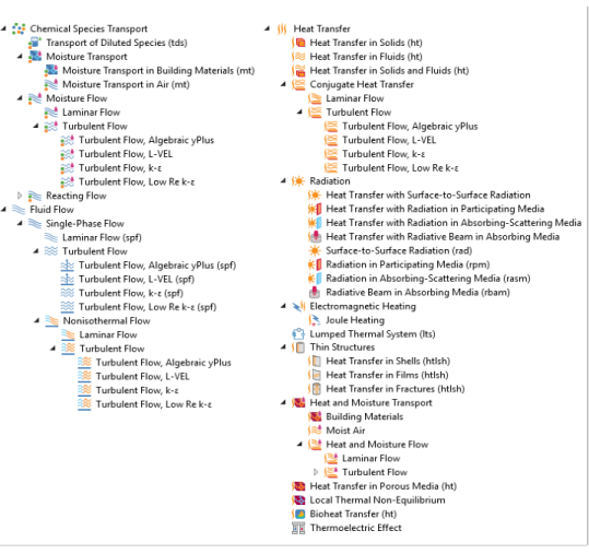
The figure below shows the heat transfer interfaces included in the Heat Transfer Module. These physics interfaces describe different heat transfer mechanisms and include predefined expressions for sources and sinks. The heat transfer interfaces are available for 1D, 2D, 2D axisymmetric, and 3D coordinate systems, and with stationary and time-dependent analyses.
Heat Transfer
By default, the Heat Transfer in Solids interface () describes heat transfer by conduction. It can also account for heat flux due to translation in solids (for example, the rotation of a disk or the linear translation of a shaft) as well as for solid deformation, including volume or surface changes. In the case of irreversible thermally induced transformation, it accounts for the enthalpy and material properties changes.
The Heat Transfer in Fluids interface () accounts for conduction and convection in gases and liquids as the default heat transfer mechanisms. The coupling to the flow field in the convection term may be entered manually in the physics interface, or it may be selected from a list that couples heat transfer to an existing fluid flow interface. The Heat Transfer in Fluids interface can be used when the flow field has already been calculated and the heat transfer problem is added afterward, typically for simulations of forced convection.
The Heat Transfer in Solids and Fluids interface () contains solids and fluids domains by default. It is aimed to simplify the setup of models where capabilities of Heat Transfer in Solids interface () and Heat Transfer in Fluids interface () are used, in particular in conjugate heat transfer applications.
The Heat Transfer in Porous Media interface () combines conduction in a porous matrix and in the fluid contained in the pore structure with the convection of heat generated by the flow of the fluid. This physics interface uses the provided power law or a user-defined expression for the effective heat transfer properties, and a predefined expression for dispersion in porous media. Dispersion is caused by the tortuous path of the liquid in the porous media. (This would be absent if the mean convective term was accounted for.) This physics interface may be used for a wide range of porous materials, from porous structures in the pulp and paper industry to the simulation of heat transfer in soil and rocks.
The Local Thermal Nonequilibrium (LTNE) multiphysics interface () is a macroscale model designed to simulate heat transfer in porous media where the temperatures in the porous matrix and the fluid are not in equilibrium. It differs from simpler macroscale models for heat transfer in porous media where the temperature difference of the solid and fluid are neglected. The absence of thermal equilibrium can result from fast transient changes, but it can also be observed in stationary cases. Typical applications are rapid heating or cooling of a porous media using a hot fluid or internal heat generation in one of the phases (due to inductive or microwave heating, exothermic reactions, and so on). This is observed in nuclear devices, electronics systems, or fuel cells for example.
The Bioheat Transfer interface () is a dedicated interface for heat transfer in living tissue. In addition to data such as thermal conductivity, heat capacity, and density, tabulated data is available for blood perfusion rates and metabolic heat sources. Tissue damage integral models based on a temperature threshold or an energy absorption model can also be included.
The Thermoelectric interface () combines the Electric Currents and the Heat Transfer in Solids interfaces with capabilities for modeling thermoelectric effects (Peltier-Seebeck-Thomson effects) as well as Joule heating (resistive heating). This multiphysics coupling accounts for Peltier heat source or sink and resistive losses in the Heat Transfer interfaces as well as for the current induced by the Seebeck effect and for the temperature dependency of material properties in the Electric Currents interface.
This physics interface is automatically paired with the AC/DC module capabilities for advanced modeling of electric effects.
Conjugate Heat Transfer
The Conjugate Heat Transfer interfaces () combine all features from the Heat Transfer and Single-Phase Flow interfaces to describe heat transfer in solids and fluids and nonisothermal flow in fluids. The heat transfer process is tightly coupled with the fluid flow problem via a predefined multiphysics coupling. These interfaces are available for laminar and turbulent nonisothermal flow and flow in porous media (Brinkman equation). For highly accurate simulations of heat transfer between a solid and a fluid in the turbulent flow regime, low-Reynolds turbulence models resolve the temperature field in the fluid all the way to the solid wall. This model is available in the Turbulent Flow, Low-Re k-ε interface (). The standard k-ε turbulence model in the Turbulent Flow, k-ε interface () is computationally inexpensive compared to the other transport two-equation turbulence models but usually less accurate. The Algebraic yPlus and L-VEL interfaces are adapted for internal flows.
With the use of the CFD Module, additional turbulence models are available. The Realizable k-ε model is similar to the standard k-ε model but has built-in realizability constraints, resulting in improved performance for certain flows, such as turbulent jets. The k-ω model is an alternative to the standard k-ε model and often gives more accurate results, especially in recirculation regions and close to solid walls. However, the k-ω model is also less robust than the standard k-ε model. The Spalart-Allmaras interface is a dedicated physics interface for conjugate heat transfer in aerodynamics, for example, in the simulation of wing profiles. The SST (shear stress transport) interface is suitable for many external flow cases and internal flows with sudden expansions. The v2-f model includes near-wall turbulence anisotropy and is giving highly accurate results.
Radiation
The heat transfer interfaces for radiation essentially belong to two different groups of radiation modeling: surface-to-surface radiation and radiation in participating or absorbing media.
The Heat Transfer with Surface-to-Surface Radiation multiphysics interface () combines the Heat Transfer in Solids interface with the Surface-to-Surface Radiation interface. It includes all functionality to model heat transfer in fluids or solids, including conduction and convection with surface-to-surface radiation. The surface-to-surface radiation model also accounts for the dependency of surface properties on the spectral bands. For example, to model the greenhouse effect, it is necessary to solve separately for ambient radiation (large wavelengths) and the sun’s radiation (small wavelengths). In addition, specular reflection can be considered instead of diffuse reflection. This is of particular interest for glossy surfaces made of polished aluminum or silver for example. Finally semitransparent layers can be modeled for configuration where a fraction of the radiation is going through a layer while the rest is reflected.
The Heat Transfer with Radiation in Participating Media multiphysics interface () combines the Heat Transfer in Solids interface with the Radiation in Participating Media interface. In includes all functionality to model conduction and convection in solids and fluids with radiation where absorption, emission, and scattering of radiation is accounted for by the radiation model.
For media that can be considered as non-emitting, the Heat Transfer with Radiation in Absorbing-Scattering Media multiphysics interface () combines the Heat Transfer in Solids interface with the Radiation in Absorbing-Scattering Media interface. For example, emission may be neglected when considering light diffusion.
For the modeling of collimated radiative beam propagating with no refraction, no reflection, and no scattering in a semi-transparent medium that is supposed not to emit in the wavelength of the incident light, the Heat Transfer with Radiative Beam in Absorbing Media multiphysics interface () combines the Heat Transfer in Solids interface with the Radiative Beam in Absorbing Media interface.
In cases where the temperature is an input of the model, more interfaces are available to compute only the radiative effects.
The Surface-to-Surface Radiation interface () describes systems where only radiation is computed, typically to estimate radiation between surfaces in space applications where the surface temperature is known.
The Radiation in Participating Media interface (), Radiation in Absorbing-Scattering Media interface (), and Radiative Beam in Absorbing Media interface () compute the radiation, with the possibility to include absorption, emission, and scattering effects, in a medium where the temperature is known.
Electromagnetic Heating
The Joule Heating interface () can combine the Electric Currents and Heat Transfer in Solids interfaces with capabilities for modeling Joule heating (resistive heating). This multiphysics coupling accounts for electromagnetic losses in the Heat Transfer interfaces as well as for the temperature dependency of material properties in the Electric Currents interface.
Lumped Thermal System
The Lumped Thermal System interface () extends the heat transfer modeling possibility to the discrete thermal systems. The external terminal feature connects a lumped thermal system to a finite element model in any dimension. This is particularly helpful to reduce dramatically the models complexity, for example to describe thermal interaction between parts in large assemblies.
Several classical devices like conductive or radiative thermal resistor are predefined. In addition advanced devices, heat pipe and thermoelectric module, and user’s defined subsystems are available.
Thin Structures
The Thin Structures interfaces () provide efficient models defined at the boundaries level but that represent thin three-dimensional domains. Three different interfaces come with different default features.
The Heat Transfer in Shells interface () contains descriptions for heat transfer in shell structures where large temperature variations may be present. Thin conductive shells correspond to the simplest model, where the shell is represented as homogeneous and the temperature differences across the thickness of the structure material are neglected. Thin layered shells can represent a multilayered structure with heterogeneous material properties and compute the temperature variation across the shell sides. Typical examples of these structures are tanks, pipes, heat exchangers, airplane fuselages, and so forth. This physics interface can be combined with other Heat Transfer interfaces. For example, the Heat Transfer in Shells interface may be used to model the walls of a tank, while the Heat Transfer in Fluids interface may be used to model the fluid inside the tank. In many cases, using the Thin Layer boundary condition, found in the Heat Transfer interfaces, produces the easiest solution.
The Heat Transfer in Films interface () implements a model to describe the temperature field in films. The simplest model for thermally thin films assumes that the temperature changes through the film thickness can be neglected. This computationally effective model is sufficient in many cases. The general model computes the temperature variation across the film. Typical applications include when the sides of the film are exposed to different temperature or when heat is dissipated in the film.
The Heat Transfer in Fractures interface () describes heat transfer in a thin porous media. The simplest model assumes that the temperature changes through the fracture thickness can be neglected, while the general model computes the temperature variation across the fracture.
Heat and Moisture Transport
The Building Materials interface () combines the Heat Transfer in Building interface with the Moisture Transport in Building Materials interface. It can be used to model different moisture variations phenomena in building components such as drying of initial construction moisture, condensation due to migration of moisture from outside to inside, or moisture accumulation by interstitial condensation due to diffusion.
The Moist Air interface () combines the Heat Transfer in Moist Air interface with the Moisture Transport in Air interface. It is used to simulate the coupling between heat transfer and vapor transport in air and the evaporation and condensation on walls.
Moisture Transport
The Moisture Transport in Building Materials interface () is used to compute the relative humidity field in building materials. It simulates moisture transport by taking in account moisture storage, liquid transport by capillary suction forces, and convective transport of vapor.
The Moisture Transport in Air interface () is used to compute the relative humidity distribution in air. It simulates moisture transport by vapor convection and diffusion in moist air and the evaporation or condensation on walls.
Moisture Flow
The Moisture Flow interfaces () combine all features from the Moisture Transport in Air and Single-Phase Flow interfaces. The Moisture Flow multiphysics coupling is automatically added. It couples the moisture transfer and fluid flow interfaces. The fluid properties may depend on vapor concentration. Models can also include moisture transport in building materials. The physics interface supports low Mach numbers (typically less than 0.3). Similarly to Conjugate Heat Transfer coupling, the moisture transport interface can be coupled with one of the turbulent flow interface.
Heat and Moisture Flow
The Moisture Flow interfaces () combine all features from the Heat Transfer in Moist Air, Moisture Transport in Air and Single-Phase Flow interfaces. Three multiphysics coupling, Heat and Moisture Flow, Nonisothermal Flow, and Moisture Flow, are also automatically added.
The Moisture Flow interfaces () are used to compute the temperature and relative humidity distribution in air along with the velocity and pressure fields.
Physics Interface Guide by Space Dimension and Study Type
The table lists additional physics interfaces that become available upon adding the Heat Transfer Module to the COMSOL Multiphysics simulation platform.
Chemical Species Transport
Moisture Transport
Moisture Flow
Turbulent Flow
Fluid Flow
Single-Phase Flow
Turbulent Flow
Nonisothermal Flow
Turbulent Flow
Heat Transfer
stationary; time dependent; thermal perturbation, frequency domain; thermal perturbation, eigenfrequency
Conjugate Heat Transfer
Turbulent Flow
Radiation
Electromagnetic Heating
stationary; time dependent; ; thermal perturbation, frequency domain; thermal perturbation, eigenfrequency
Thin Structures
Heat and Moisture Transport
Heat and Moisture Flow
Turbulent Flow
stationary; time dependent; thermal perturbation, frequency domain; thermal perturbation, eigenfrequency
1 This physics interface is included with the core COMSOL package but has added functionality for this module.
2 This physics interface is a predefined multiphysics coupling that automatically adds all the physics interfaces and coupling features required.
3 Requires the addition of the CFD Module.