Use the Electrode Surface node to model an electrochemical electrode-electrolyte interface between an electrolyte domain and an electrode boundary where the electrode is not included explicitly as a domain in the model geometry. Set the electric potential of the electrode or specify a current condition that the potential of the electrode shall fulfill, and use subnodes to specify the
Electrode Reaction and the
Double Layer Capacitance at the interface.
Specify either a Surface resistance Rfilm (SI unit:
Ω·m
2) directly or choose the
Thickness and conductivity option to calculate the surface resistivity based on a depositing film thickness.
The perturbation parameter is either Electric potential,
Electrode potential,
Total current,
or
Average current density, based on the
Boundary condition selected in the next section.
Use the Electric potential option to set the value of the potential explicitly with respect to ground whereas the
Electrode potential will set the potential value with respect to a reference potential.
Total current,
Average current density, and
External short all add an extra global degree of freedom for the potential in the electrode phase, set to comply with the chosen condition.
When using the Total current option in 1D or 2D, the boundary area is based either on the
Cross-sectional area (1D), or the
Out-of-Plane thickness (2D) properties, set on the physics interface top node.
See also the documentation for the Electrode Potential and
External Short nodes for further information about these boundary condition.
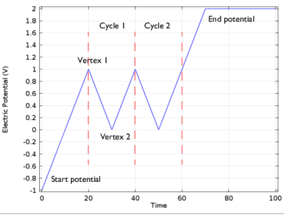
The Cyclic voltammetry setting varies the electric potential linearly in time as follows when used in conjunction with a
Cyclic Voltammetry study step:
More advanced waveforms can be obtained using the Electric potential option with a parameter setting based on
Functions found in the
Definitions menu.
This boundary condition is only available for the Electroanalysis charge conservation model in the
Tertiary Current Distribution, Nernst-Planck (tcd) interface.
The Counter electrode option will set a potential to ensure an overall charge balance of the cell so that the integral of all electrode reaction currents of all electrode surface node sums up to zero.
If Cyclic voltammetry is selected as the
Boundary condition, the
Smoothing of cyclic voltammetry wave functions check box is selected by default and the
Smoothing factor defaults to 1·10
-3. When enabled, smoothing is applied on the triangular wave around the vertex potentials. The smoothing zone corresponds to the product of the smoothing factor with half the duration of one period of the triangular wave.
This section is only available in the Primary Current Distribution and Secondary Current Distribution interfaces when the Current Distribution Model property has been set to
Primary. To display this section, click the
Show More Options button (

) and select
Advanced Physics Options in the
Show More Options dialog box.