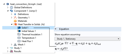
For each physics node there is an Equation section that is available by default on the
Settings window. This section has options to display mathematical equations applicable to the node.
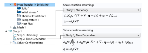
The display options available from the lists depend on the study types and other physics-specific factors. See Figure 3-20 for an example comparing the equations that display for a
Stationary or
Time Dependent study for a
Heat Transfer in Solids interface. Some
Settings windows do not have any options and only display the relevant equation and other windows have additional sections that become available for the
Equation display based on the study type selected.
When you add physics interfaces to a Component, the supported Study types are listed in the
Equation form list.
Study controlled is the default; select another option as needed. When the setting is
Study controlled, the study controls the equation form — stationary or time dependent, for example — for the physics interface. In some cases, that equation form might not be compatible with the physics covered by the physics interface; the physics interface then uses its default equation form (typically, a stationary equation form). You can then instead choose one of the supported study types.
The Show equation assuming option is available by default when
Study controlled is selected (or left as the default) as the
Equation form. Options availability is based on the studies added and defined for the model.
This option is available if Frequency domain is selected as the
Equation form. The default uses the frequency
From solver. If
User defined is selected, enter another value or expression (SI unit: Hz).
This option is available if Mode Analysis or
Boundary Mode Analysis is selected as the
Equation Form. Enter a value or expression in the field (SI unit: Hz). Specify a frequency (it is not present as a solver variable).
This option is available with the RF Module Electromagnetic Waves interface and if
Boundary Mode Analysis is selected as the
Equation Form. Enter a value in the field (unitless).
 ) and clear the Equation Sections check box in the Show More Options dialog box.