The solver prints a message about inverted curved elements to the Messages window and corresponding warnings to the
Log window if they appear.
Warnings nodes (

) also appear in the solver sequence where the inverted mesh elements appear. If you are using a
Free Tetrahedral node to create the mesh, it is often possible to avoid inverted curved elements by selecting the
Avoid inverted curved elements check box in the node’s
Settings window under
Element Quality Optimization.
For a moving mesh, the mesh can become inverted, in which case an error occurs. In the Error node (

), which appears in the solver sequence, information about the location of the inverted elements appears. The problematic mesh is available as a
Problematic Deformed Mesh node (

) under
Meshes, so that you can inspect the mesh around the coordinates for the inverted mesh elements.
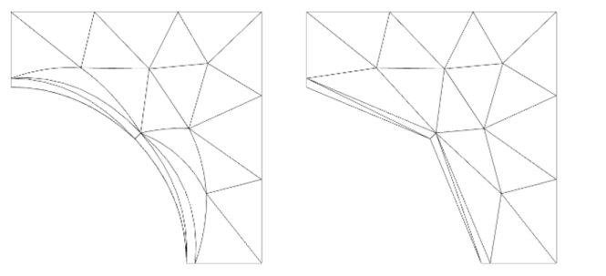
In many situations, the inverted elements can be fixed by curving elements inside the domain to match the boundary. You find the Avoid inverted elements by curving interior domain check box, which controls if elements inside the domain are curved, in the
Settings window for the
Component node. The default behavior is to curve interior domain elements when needed. In 3D, this setting also has the effect that elements inside a face can be curved to match the face edges.
The geomapproxdist variable indicates, for each element, how far a node point in the element was moved from the geometry. To see the parts of the geometry that are affected, you can make a surface plot of
geomapproxdist, or make a volume plot with an element filter set to
geomapproxdist>0.
The variable linearizedelem is 1 in elements that are linearized and 0 elsewhere. You can use this variable to identify mesh elements with linearized elements. For example, use
linearizedelem as the expression in a plot.
If the method used to avoid inverted elements fails, it may happen that inverted elements are present in the mesh you solve on, as described in the first section. You can visualize inverted mesh elements using the built-in reldetjacmin variable, which is the minimum (over each element) of the determinant of the Jacobian matrix for the mapping from the straight mesh element to the possibly curved mesh element used by the solver. A minimum value less than zero for an element means that the element is wrapped inside-out; that is, it is an inverted mesh element.
A typical visualization uses reldetjacmin as the quantity to plot as a volume plot. To display only the inverted elements, add a
Filter subnode using the logical expression
reldetjacmin<0 to include only the inverted elements or
reldetjacmin<0.2 to include also highly curved elements.
If you experience inverted mesh elements while meshing or while importing meshes, you usually do not have a solution. In such cases, create a Mesh Plot with the logical expression qual<eps instead because
reldetjacmin is not available. The plot then shows both the inverted mesh elements, for which the mesh quality is negative, and the totally degenerated elements, for which the mesh quality is zero or very close to zero.
If you use reldetjacmin, the plot shows the quality of higher-order elements (if any), while
qual always uses linear elements.