Mesh Elements for 1D, 2D, and 3D Geometries
Mesh Element Numbering Conventions in the COMSOL Multiphysics Programming Reference Manual.
1D Geometries
The mesh generator discretizes the domains (intervals) into smaller intervals (or mesh elements). The endpoints of the mesh elements are called mesh vertices.
The boundaries (or vertices) defined in the geometry are represented in the mesh by boundary elements (or vertex elements).
2D Geometries
The mesh generator discretizes the domains into triangular or quadrilateral mesh elements. If the boundary is curved, these elements represent an approximation of the original geometry. The sides of the triangles and quadrilaterals are called mesh edges, and their corners are mesh vertices. A mesh edge must not contain mesh vertices in its interior.
The boundaries defined in the geometry are discretized (approximately) into mesh edges, referred to as boundary elements (or edge elements), which must conform with the mesh elements of the adjacent domains.
The geometry vertices are represented by vertex elements.
3D Geometries
The mesh generator discretizes the domains into tetrahedral, hexahedral, prism, or pyramid mesh elements whose faces, edges, and corners are called mesh faces, mesh edges, and mesh vertices, respectively.
The boundaries in the geometry are discretized into triangular or quadrilateral boundary elements. The geometry edges are discretized into edge elements.
Similar to 2D, the geometry vertices are represented by vertex elements.
Conforming Meshes
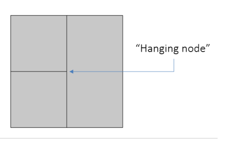
Meshes generated in the COMSOL Multiphysics software are conforming. In a conforming mesh, the intersection between any two elements in the mesh is a subelement (mesh face, mesh edge, or mesh vertex) of both, or nothing. For geometries of assembly type this definition is only valid for each individual part of the assembly. A nonconforming mesh, which can be the case for an importing mesh, typically contains “hanging nodes” (see Figure 8-1 below).
Figure 8-1: A “hanging node” in a nonconforming mesh.