The physics interface and its layer features have a section named Shell Properties. The layer selections made in this section interact with the standard selections of geometrical objects (boundary, edges, or points) in order to provide a complete specification of where a material property or boundary condition is to be applied.
The default selections in the Shell Properties section differ between different physics features. This reflects the fact that some physics features (such as thermal expansion) are more likely to be applied to all layers, whereas other features (such as added mass) are more likely to be used for a single layer or interface.
The section always contains a check box named Use all layers. When selected, you cannot control individual layers; the contribution is given to all layers. All information is taken from the definitions made in the layered material features (
Layered Material Link,
Layered Material Stack, or
Single Layer Material) under
Materials in the current component. This means that a single physics node can accommodate several different stacking sequences. As geometrical selection, you can use any object selected in any of the layered material features.
When Use all layers is not selected, the
Layer list is displayed. You can select
If you select an individual Layered Material Link,
Layered Material Stack, or
Single Layer Material, you can only select geometrical objects which are part of the selections of that feature. In most cases, you will then get access to a list of check boxes where you can further limit the contributions to individually selected layers to which this contribution is to be added.
The interface features have a section named Interface Selection. The interface selection can be done by choosing from the following options:
When Selected interfaces is chosen, the
Interface list is displayed. You can select
If you select an individual Layered Material Link,
Layered Material Stack, or
Single Layer Material, then you can only select geometrical objects which are part of the selections of that feature. In most cases, you will then get access to a list of check boxes where you can further limit the contributions to individually selected interfaces to which this contribution is to be added.
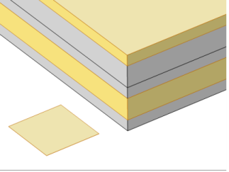
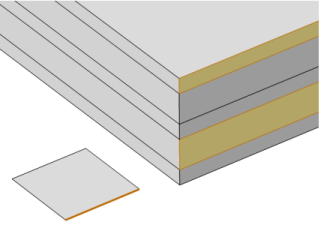
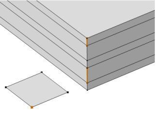
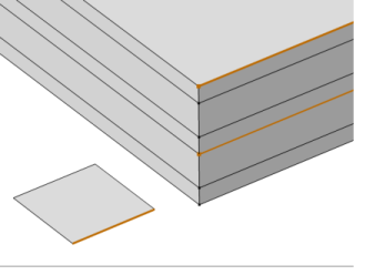
This is illustrated in Figure 3-16 to
Figure 3-18 where the patch at the lower left is the actual shell, and the 3D sketch shows an expanded view of what it would represent in the physical world.
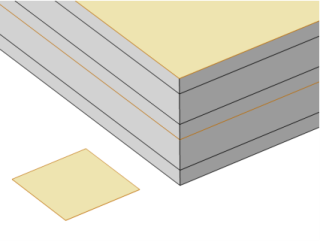
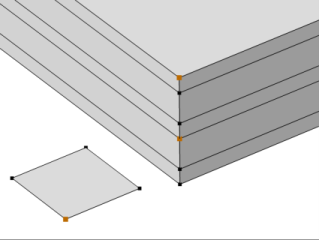
This is illustrated in Figure 3-19 to
Figure 3-21 where the patch at the lower left is the actual shell, and the 3D sketch shows an expanded view of what it would represent in the physical world.