This model has been developed as a lowest-order, reasonable approximation to experimental data in Ref. 27 (see their Figure 9). It consists of a simple serial
RCL circuit applied on a transducer area of
At, and has the impedance
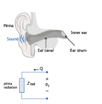
This impedance describes the acoustic radiation losses from the pinna (also known as the auricle, this is the visible part of the ear which is exterior to the head), see Figure 2-10. For cases where you model the ear canal explicitly using pressure acoustics, this boundary condition describes the acoustic losses from the outward acoustic radiation from the ear canal and into the surrounding air.
The parameter values are given in Table 2-8. Note that the value of

is not reported in the papers
Ref. 28 to
30, but has instead been read off during model implementation.
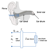
This model accounts for the acoustic losses associated with the ear canal and the entire human ear, see Figure 2-12. It does not include the radiation losses associated with the pinna, the visible part of the ear which is external to the head.
Here, Zeardrum is the eardrum impedance defined in
Equation 2-27 and
cij are the components of the ear canal two port
C. The ear canal is treated as
Ntot small segments each with length
Δk and radius
rk so its two port
C is given by
In these expressions, γ is the ratio of specific heats,
Γk is the propagation constant (“wave number”) of the
kth ear canal segment which has the segment-specific attenuation
αk,
is the Prandtl number expressed in terms of the specific hear Cp, dynamic viscosity
μ, and thermal conductivity
k. Notice that the papers presenting the model (
Ref. 28 to
30) do not exactly specify which expression for the attenuation constants
αk is being used, but only refer to
Ref. 31. The expression above for
αk is the most general expression taken from this paper. The values for
Δk and
rk are listed in
Table 2-9.
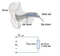
The pressure at the eardrum peardrum is calculated whenever this impedance boundary condition is applied. This pressure is available in the plot group, and is calculated from the expression
where pt is the pressure on the boundary,
cij are the coefficients of the ear canal two port
C and
Zear w/o pinna is the ear impedance;
C and
Zear w/o pinna are defined in
Equation 2-28 and
Equation 2-29 above.
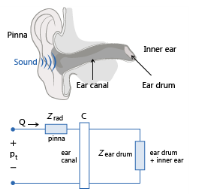
This model accounts for all acoustic losses associated with the entire human ear, both the internal parts as well as the pinna, the visible, external part of the ear on the head, see Figure 2-13. The model does not include any information about the directivity of the ear (the head related transfer functions, HRTFs) which depends on the ear geometry at higher frequencies. It is valid in the low frequency limit and for normal incidence on the ear. It is given by
The pressure at the eardrum peardrum is calculated whenever this impedance boundary condition model is applied. This pressure is calculated from
Zear full using the expression


 .
.

 ,
,
 .
.