Mesh Guidelines
When setting up a mesh for a Ray Acoustics simulation the following guidelines should be followed:
When rays may interact with curved boundaries (either reflection or refraction), the accuracy of the reinitialized ray trajectory (that is, the reinitialized wave vector k) depends on the mesh. To create a very fine mesh on curved surfaces without making the mesh unnecessarily fine elsewhere, use the Curvature factor in the Size settings window. The closer this number is to zero, the finer the mesh will be on a curved surface. A value of 0.1 seems adequate for most applications. If there are small, tightly curved surfaces in the model, it might also be necessary to reduce the Minimum element size to allow the small curvature factor to do its job.
Domains that are not included in the selection for the Ray Acoustics interface do not need to be meshed. However, a boundary mesh must always be defined wherever any boundary condition is applied. In addition, it is assumed that the speed of sound and density in all deselected domains are the Speed of sound in exterior domains and Density of exterior domains, which are specified in the physics interface Ray Release and Propagation section. Thus, media with graded or temperature-dependent material properties must always be included in the selection of the Ray Acoustics interface, and they must always be meshed.
Accumulator features (both on surfaces and on domains) work by defining additional dependent variables using constant shape functions. When using an Accumulator on a Wall, for example, the contribution from each ray is distributed uniformly over whatever boundary element it hits. If the mesh on the boundary is very fine, this will make the value of the accumulated variable look noisy unless the number of rays hitting the boundary is much larger than the number of boundary elements.
Representation of Curved Surfaces
When rays reach the boundaries of geometric entities in a model, they do not interact with an exact parameterized representation of the geometry. Rather, they propagate through the mesh elements that discretize the modeling domain and interact with the boundary elements that cover the surfaces of the geometric entities.
When the surfaces of the geometry are flat, the shape of the surface mesh is indistinguishable from the shape of the geometric entities themselves. Therefore, the fact that rays interact with the mesh instead of the geometry does not introduce any discretization error, and it is possible to accurately compute ray trajectories even when the mesh is extremely coarse.
Curved surfaces in the geometry, however, usually incur a significant amount of discretization error when predicting how rays will interact with them. The time and location at which the ray interacts with the boundary mesh element might be slightly different from the time at which it would have interacted with an exact representation of the surface. In addition, the tangential and normal directions on the boundary mesh element may differ from the tangential and normal directions on the surface, affecting the accuracy of boundary conditions that involve the tangential and normal directions, such as the Specular reflection condition.
The order of the curved mesh elements used to determine the geometry shape is controlled by the Geometry shape order list in the Model Settings section of the Settings window for the main Component node. If Automatic, the default, is selected, the curved mesh elements are usually represented by quadratic curves; in some cases, linear functions are used to prevent inverted mesh elements from being created.
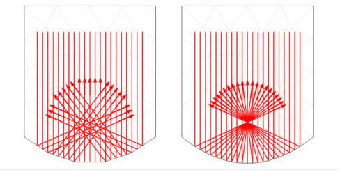
The effect of the geometry shape order is most notable on a coarse mesh, as shown in Figure 8-6. The mesh elements are shown as pale gray lines in the background and the ray trajectories are represented as thick red arrows. The rays initially propagate downward and are specularly reflected by a parabolic surface. If Linear is selected from the Geometry shape order list, all rays that hit the same boundary element are specularly reflected in the same direction, as shown on the left. Even though the bottom surface is parabolic, the rays don’t all intersect at a single focus due to the discretization error. If Quadratic or Automatic is selected, rays that hit the same boundary element can still be reflected in different directions because the tangential and normal directions can vary along the surface of the curved element. As a result, the rays reflected by the parabolic surface all intersect at a well-defined focal point as expected.
Figure 8-6: Comparison of rays being specularly reflected at a curved boundary represented using linear elements (left) and quadratic elements (right).
Ray Tracing in an Imported Mesh
It is also possible to compute ray trajectories in an imported mesh. The mesh can be imported from a COMSOL Multiphysics file (.mphbin for a binary file format or .mphtxt for a text file format) or from a NASTRAN file (.nas, .bdf, .nastran, or .dat).
If the mesh is imported from a COMSOL Multiphysics file, the imported mesh always uses linear geometry shape order for the purpose of modeling ray-boundary interactions, even if the model used to generate the mesh had a higher geometry shape order.
If the mesh is imported from a NASTRAN file, the ray-boundary interactions may be modeled using either linear or higher geometry shape order. If Export as linear elements is selected when generating the NASTRAN file, or if Import as linear elements is selected when importing the file, then linear geometry shape order will be used.